MC_CombineAxes (FB)
FUNCTION_BLOCK MC_CombineAxes
This function block combines the motion of 2 axes into a third axis with selectable combination method.

Basically it is a calculation of a new position setpoint based on the two position setpoints of the input axes. This function block is reflected in the state diagram like a synchronized motion type. As application example one can work with a separate profile synchronized to an object on a moving belt, or a rotating knife with flexible covered distance to be cut.
Note
To stop the motion, the function block has to be interrupted by another function block issuing a new command.
- Example of Ice-cream
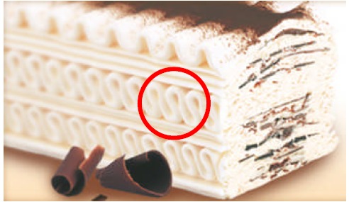
MC_CombineAxes can generate special synchronized movements that are not possible or complex to generate in other ways. In the following example, a CAM function block and the result of a Gear function block are both synchronized to a conveyor master, are added to generate a virtual master for a MC_GearInPos function of the final axis that will execute the movement. The particular application of this example could be a machine to deposit the icecream waving layers on top of the icecream base travelling through the freezer line in icecream factory. The dosing axis has to synchronize with a waving manner to the conveyor carrying the icecream base block. And it has to do this in a particular starting position and wave phase to achieve the expected result (therefore the GearInPos). With the CAM function block one can define different wave patterns easily (like the one longer in the top of icecream).
Another case application can be chocolate bars with decoration (individual bars in mouldings). The dosificator makes the wave synchronized with conveyor and returns for the next
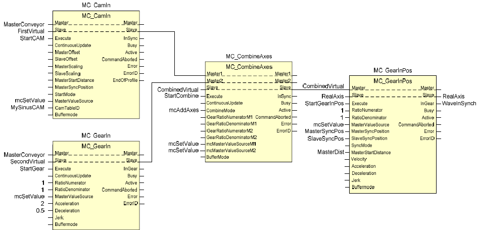
- Application example of MC_CombineAxes
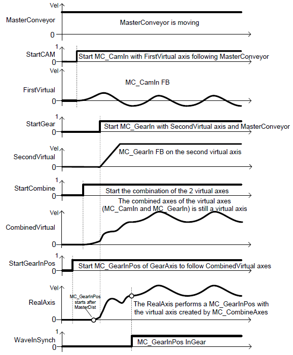
- The corresponding timing diagram for MC_CombineAxes example
Note
This block has to be called within the REAL-TIME task, same task as CMC_BASIC_KERNEL
- InOut:
Scope
Name
Type
Comment
Input
ExecuteBOOLStarts the function block at rising edge
CombineModeBOOLFALSE = Addition of two input axes positions, TRUE = Subtraction of two input axes positions
GearRatioNumeratorM1INTGear ratio numerator for master axis 1 towards the slave
GearRatioDenumeratorM1INTGear ratio denominator for master axis 1 towards the slave
GearRatioNumeratorM2INTGear ratio numerator for master axis 2 towards the slave
GearRatioDenumeratorM2INTGear ratio denominator for master axis 2 towards the slave
MasterValueSourceM1Decide to use the actual position or reference position of master axis 1. mcSetValue: Synchronization on master set value. mcActualValue: Synchronization on master actual value
MasterValueSourceM2Decide to use the actual position or reference position of master axis 2. mcSetValue: Synchronization on master set value. mcActualValue: Synchronization on master actual value
AccelerationLREAL[u/s°°2] Value of the acceleration (increasing energy of the motor), just applied until “insync” is reached. Range: >0. If value = 0, Acceleration will be equal to parameter paraMaxAccelerationAppl.If value > 0 and <= 1,Acceleration will be limited to 1.
DecelerationLREAL[u/s°°2] Value of the deceleration (decreasing energy of the motor), just applied until “insync” is reached. Range: >0. If value = 0, Deceleration will be equal to parameter paraMaxDecelerationAppl.If value > 0 and <= 1,Deceleration will be limited to 1.
BufferModeNot supported, default mcABORTING used
Output
InSyncBOOLCommanded gearing completed
BusyBOOLThe function block is not finished
ActiveBOOLIndicates that the function block has control on the axis
CommandAbortedBOOLCommand is aborted by another command from other PLCopen function block
ErrorBOOLSignals that error has occurred within function block
ErrorIDError identification. For error details refer to Enumeration ERROR_ID
Inout
Master1Reference to master axis 1
Master2Reference to master axis 2
SlaveReference to slave axis
Structure: