MC_StepAbsSwitch (FB)
FUNCTION_BLOCK MC_StepAbsSwitch
This function block performs a homing function by searching for an absolute positioned external physical switch. An Absolute Switch has two “Off” or “On” areas, see example.
For central Motion Control implementation: The signal of the Absolute Switch has to be written to the variable “absRefSwitch” of the data type CMC_Axis_IO

Note
Inside the operation area the limit switches have to be logically FALSE and outside the borders the signal of the corresponding limit switch has to be logically TRUE. If needed the signal from the sensor must be inverted before it is connected to an element the CMC_Axis_IO data type
- Example
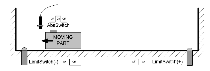
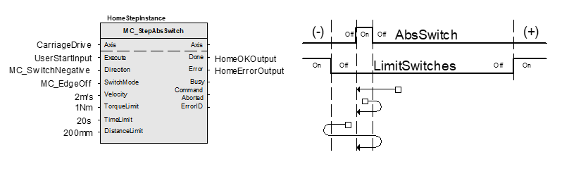
This physical layout has the risk that homing is started in the wrong direction (escaping the switch). To support such case, it implements a special behavior when Limit Switches are found (or the AbsSwitch itself is “On” at Execute)-
Axis State is set to Homing,
The homing is commanded in the most likely direction were the sensor can be found. In this example(-),
The velocity is defined by the input,
Both time and distance limits can cause an error if exceeded,
If any LimitSwitch is found during Homing (any of them), then a special process is started in the opposite direction, the AbsSwitch is searched to switch off (or “On” depending on SwitchMode setting). The Edge (passed by), and homing process is restarted in the original direction and with the same conditions. This ensures that the end conditions are always same,
If the SwitchMode is either MC_SwitchNegative or MC_SwitchPositive, then the special process is also started in opposite direction depending from the switch state at “Execute”,
The direction changes only when the specified Velocity is reached (InVelocity),
This function block does not modify the actual position,
This function block does not leave the Homing State when done.
This function block can only be used once for a homing sequence

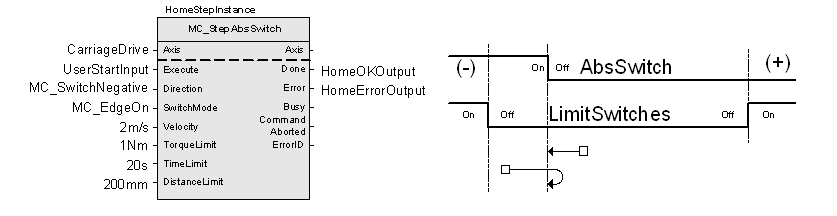
An overlapping switch configuration is also possible. This has same the behavior as working on the limit switches
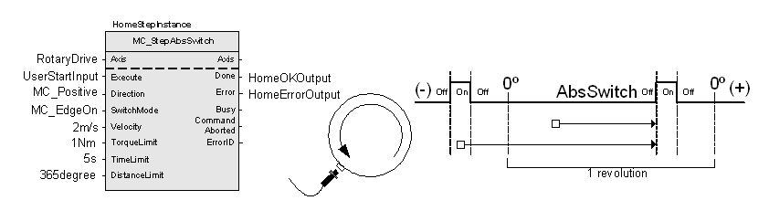
If the input direction is set to a fixed direction (MC_Positive or MC_Negative), then the initial switch state is ignored (used for example in rotary axis where only one sense of rotation is allowed):
Note
With an overlapping switch configuration either MC_EdgeOn or MC_EdgeOff can be used for the input SwitchMode. This depends on the switching behaviour of the absolute switch and the used option for the input Direction
- InOut:
Scope
Name
Type
Comment
Input
ExecuteBOOLStarts the function block at rising edge
Direction- Specifies the direction of the motion if any:
MC_Positive = Starts in positive direction always
MC_Negative = Starts in negative direction always
MC_SwitchPositive = Depends on Switch status at Execute edge. If Switch is “Off”, direction is positive, if “On” it is negative
MC_SwitchNegative = Like previous, but opposite
SwitchMode- Sensor condition to finalize this function block in any switch mode:
MC_On = When sensor is ON.
MC_Off = When sensor is OFF.
MC_EdgeOn = When Off to On transition in sensor
MC_EdgeOff = When On to Off transition in sensor
VelocityLREAL[u/s] Value of the maximum velocity (not necessarily reached). Range: >0
AccelerationLREAL[u/s°°2] Value of the acceleration (increasing energy of the motor). Range: >0.If value = 0, Acceleration will be equal to parameter paraMaxAccelerationAppl.If value > 0 and <= 1,Acceleration will be limited to 1.
DecelerationLREAL[u/s°°2] Value of the deceleration (decreasing energy of the motor). Range: >0.If value = 0, Deceleration will be equal to parameter paraMaxDecelerationAppl.If value > 0 and <= 1,Deceleration will be limited to 1.
TorqueLimitLREALNot supported
TimeLimitLREAL[s] If the function block condition is not met in the TimeLimit, an error is issued. <=0: No time limit
DistanceLimitLREAL[u] If the function block condition is not met within a DistanceLimit travel, an error is issued. 0 = No distance limit
BufferModeNot supported, default mcABORTING used
Output
DoneBOOLShows the status of the function block. Done = TRUE if the execution is finished
BusyBOOLThe function block is not finished
ActiveBOOLIndicates that the function block has control on the axis
CommandAbortedBOOLCommand is aborted by another command from other PLCopen function block
ErrorBOOLSignals that error has occurred within function block
ErrorID- Error identification. For error details refer to Enumeration ERROR_ID
Specific Error numbers: + MC_TimeLimitExceeded + MC_DistanceLimitExceeded + MC_TorqueLimitExceeded
Inout
AxisReference to axis
Structure: