SolarEncoderCD522 (FB)
FUNCTION_BLOCK SolarEncoderCD522 EXTENDS AbbLConC3
Function block to easily integrate, with the CD522 IO module, incremental encoders (A, B, Z) as positioning sensors for Solar Trackers.
The module CD522 can be used in 12 different configurable operating modes. The operating mode is configured in PLC Configuration using module parameters. After that, it is activated during the initialization phase (power-on, cold start, warm start).
In order to configure and use the function encoder of module CD522, different operating modes are available. The function block SolarEncoderCD522 should be used by configuring the parameter 6 or 14 (“Mode counter 0” or “Mode counter 1”) in modes 11, 12 or 13 to use the incremental encoder as: Incremental encoder, Incremental encoder X2 or Incremental encoder X4 respectively
To Configure, Configuration -> Devices -> IO Bus -> CD522 -> CD522 IO Mapping -> Map variable for position sensors
Note
Please refer to Automation Builder help for CD522 module configuration and parameter details.
Example configuration of the module is described in the example project and example documentation.
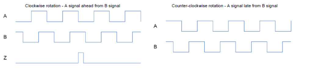
The module CD522 provides 2 encoder functions for relative positioning with 3 signals. 2 signals are used for rotation discrimination and pulse count, identified by A0 and B0 for counter0 and A1 and B1 for counter1. The third one is used in multi-turn encoder to count the number of rotation (mechanical zero), identified by Z0 for counter0 and Z1 for counter1. Signals Z0 and Z1 are used in synchronization process. Inputs I3 and I11 needs to be defined as touch input.
Note
If the setup needs both Calibration & Synchronization then the Z pulse from the encoder to be connected to both Z0 & I3 inputs for counter0 and Z1 & I11 inputs for counter1.
- Example
The rotation is identified with a shift angle (90°) between A and B signal. In the module CD522, the clockwise rotation is identified with A signal in advance to B.
Depending on which kind of operating mode is specified, the counting procedure will be x1, x2 or x4 count. Basically the x1 counting mode is used (mode 11). The encoder module discriminates the rotating way and count one pulse for each rising edge of the A signal.
In order to increase resolution, the x2 counting mode can be specified (mode 12). The encoder module counts both the positive edges and the negative edges of trace A. This results in the double number of counting pulses. The precision increases correspondingly.
The resolution could be multiplied by 4, using the x4 counting mode (mode 13). The encoder module counts a pulse on both rising and falling edge of A signal and B signal.
- InOut:
Scope
Name
Type
Initial
Comment
Inherited from
Input
EnableBOOLFALSE
A rising edge (Enable = TRUE) starts the operation, the output Busy goes to TRUE. All other inputs are read and considered continuously. Execution will continue forever until a falling edge (Enable = FALSE) aborts the operation. During Aborting the Busy is still TRUE. Afterward all outputs are reset.
AbbLConC3
Output
BusyBOOLFALSE
Operation is running (while output Error is FALSE)
AbbLConC3
ErrorBOOLFALSE
Operation is stopped with error (while output Busy is FALSE). This output is TRUE for at least one cycle or until Enable is set to FALSE. The output ErrorID gives more details about the error.
AbbLConC3
Input
CounterNumWORD0
2: Indicates which counter to be used. 0: counter 0, 1: counter 1.
EnableCounterBOOLFALSE
- 3: TRUE: pulse counting of counter is enabled. FALSE: no pulse counting is performed and the pulses are lost.
If counting has already started and if EnableCounter = FALSE, the pulse counting stops and counter value PosAct is stored.
If EnableCounter = TRUE again, the pulse counting will start again and counter value PosAct will continue since previous value.
While EnableCounter = TRUE, it is possible to modify the stored value in PosAct variable. When EnableCounter = TRUE again, counter value PosAct will continue since previous value
SetStartBOOLFALSE
4: If TRUE, counter takes values from input SetStartValue to transfer it to PosAct. After that, RdySet = TRUE. As long as input SetStart = TRUE, no pulses are counted because the counter is always overwritten by the input SetStart
SetStartValueREAL0
5: 32 bit start counter value
EnableCalibBOOLFALSE
- 6: Enabling calibrating process
If EnableCalib = TRUE, when a rising edge is detected at the encoder´s reference point(Z) signal, output ZValue will take the stored value in PosAct and output RdyCalib is set to TRUE. If this input is continuously TRUE, only one calibrating process will be done even system reaches encoder´s reference point(Z) once again. In order to enable another calibrating process, input EnableCalib has to be set to FALSE and set to TRUE again.
Calibrating process is executed out of CPU cycle, and it is able to detect the multiple rising edges that appear when a simple limit switch is used. Due to that, it is recommended to use devices assembled especially for this purpose (high accuracy limit switch). Inputs used as reference point Z in the calibrating process are: Counter0 -> I3, Counter1 -> I11
EnableSyncBOOLFALSE
- 7: Enabling synchronizing process
If input EnableSync = TRUE, when a rising edge is detected at the encoder´s reference point(Z) signal, output PosAct will take the value stored at ZValue, output RdySync is set to TRUE only during a program cycle. While EnableSync is set to TRUE, PosAct output will take the value stored at ZValue every time that a rising edge is detected at the encoder´s reference point(Z) signal.
Inputs used as reference point Z in the synchronisation process are: Counter0 -> Z0, Counter1 -> Z1.
MeasuringStepREAL0
- 8: Indicates the resolution of the encoder device (see technical data from manufacturer). Format: Degrees
For example, using an incremental encoder with resolution of 10000 pulses each 360° and x4 counting mode (software configuration), measuring step will use the following value: 360 / (4 x 10000) = 0,009.
Inout
CounterInARRAY [0..11] OF WORD
9: Array of WORD for input of Configuration fast counter
CounterOutARRAY [0..15] OF WORD
10: Array of WORD for output of Configuration fast counter
PosActREAL- 11: The current position (actual position) can be retrieved at any time using the output PosAct.
Note
If a shutdown occurs, value of actual position will be lost. Hence, parameter must be declared as a retain variable.
If communications problem occurs between CPU and module CD522, position value stored in PosAct will be lost.
ZValueREAL12: Indicates the position of the encoders reference point (Z). The user is able to configure where the Z position is, Format: Degrees
Output
ErrorIDNO_ERROR
3: Error number
RdySetBOOLFALSE
4: When the action of SetStart finishes, RdySet is set to TRUE for only one cycle
RdyCalibBOOLFALSE
5: The output RdyCalib displays ready message of calibrating process. While input EnableCalib is set to TRUE, RdyCalib = TRUE. If EnableCalib = TRUE and rising edge is detected at ZPulse signal, RdyCalib will be TRUE until EnableCalib = FALSE.
RdySyncBOOLFALSE
6: Displays the ready message of the synchronisation process. It is set to TRUE only for one cycle
ZPulseBOOLFALSE
7: encoder’s reference position Z reached. This signal is only visible if programs execution time is slower than the signal of encoder’s reference point (Z).
Methods:
D_AbortAction
A_StartAction
B_CyclicAction
C_CleaningAction
E_ResetAction
Structure: