


|
This is the web edition of the original ⮫ AC500-S safety user manual, version 1.3.2. This web edition is provided for quick reference only. The original safety user manual must be used to meet functional safety application requirements. |
Instantiate safety and non-safety modules, which are a part of the "black channel" for safe communication and do a proper configuration of those. Define variable names for input, output and PROFIsafe signals in accordance with the safety programming guidelines.
-
Select one of four slots available for communication modules and safety CPU and instantiate a safety CPU on it. Note, that the slot number shall be the same as the physical slot number on which safety CPU is attached.
-
Double-click on the safety CPU and set its parameters, as needed.

NOTICE
Pay attention to the parameter “Enable debug”. If this parameter is set to “Off”, then no new boot project can be loaded to the safety CPU.
-
To have remote stations in the system, we can instantiate PROFINET IO controller communication module CM579-PNIO, for example, in slot 2. Note that PROFINET is the only bus which is supported for PROFIsafe communication in AC500-S safety PLC.
-
Now, select newly created CM579-PNIO module and instantiate the required number of PROFINET modules, e.g., CI501-PNIO, CI502-PNIO, etc. or any 3rd party PROFINET modules previously imported in the “Device Repository” using GSDML files.
⮫ Details on the setting of proper PROFINET device names and IP addresses.
NOTICE
When using CI501-PNIO or CI502-PNIO with safety I/O modules with firmware V1.0.0, set the parameter “IO-BUS Reset after PROFINET reconnection” = OFF on CI502-PNIO or CI501-PNIO.
“IO-BUS Reset after PROFINET reconnection” = ON is not recommended and permitted only for special use cases. Contact ABB technical support for more details.
-
On “IO_Bus” object, one can instantiate up to 10 I/O modules (safety or non-safety ones) located centrally on the non-safety CPU.
-
Similarly, up to 10 I/O modules (safety and non-safety) can be instantiated on any ABB PROFINET IO device.
GSDML file defines the maximum number of supported modules on 3rd party PROFINET IO devices.
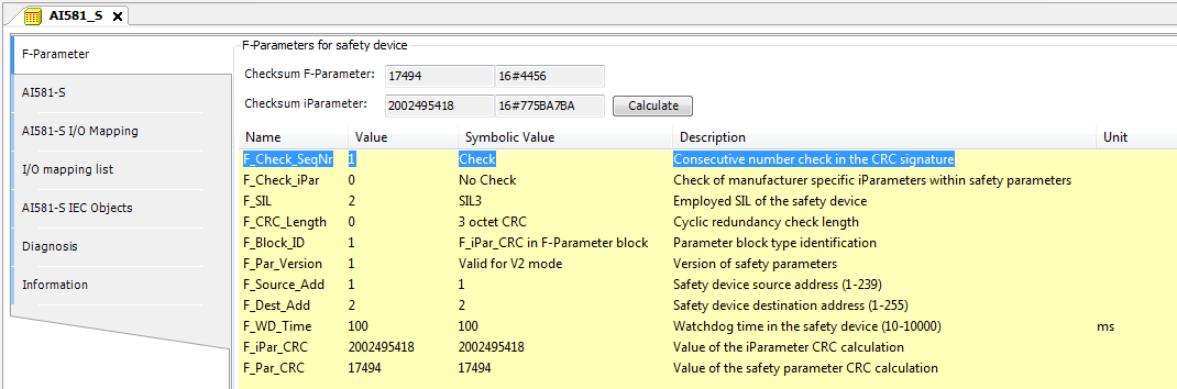
Parameters of safety I/O modules can be set using double-click on those modules. Each module has two types of parameters: F-Parameters and iParameters.
F-Parameters are parameters which were specially defined by PROFIsafe group ⮫ [2] to realize safe device communication and parameterisation. F-Parameter names are the same for all F-Devices (ABB and 3rd party devices). The most important of them for end-users are explained here.
- F_SIL
-
defines the highest useable safety integrity level for the given F-Device. It shall not be higher than the defined value in the GSDML file of the F-Device.
- F_Dest_Add
-
defines the F-Device address which shall be the same address as the one set on the physical safety I/O device.
NOTICE
Make sure that F_Dest_Add is set unique for all F-Devices, otherwise no valid safety configuration can be generated.
Decimal or hexadecimal number with a prefix 16# or 0x can be used to set F_Dest_Add in Automation Builder.
- F_Source_Add
-
defines the F-Host address which shall be valid for the given F-Device.
- F_WD_Time
-
defines the watchdog timeout on the F-Device connection. It is supervised on both F-Host and F-Device. If the F-Host detects a timeout, the F-Device will be passivated and fail-safe values will be sent. If the F-Device detects a timeout, he indicates it to the F-Host via PROFIsafe status byte and sends fail-safe values. F_WD_Time is further used in safety function response time calculations.
- F_CRC_Seed
-
defines the supported PROFIsafe protocol version. If F_CRC_Seed does not exist or F_CRC_Seed = 0 in the GSDML (default, symbolic value "CRC_Seed16"), the PROFIsafe protocol version V2.4 is supported from the F-Device and the improvements introduced with PROFIsafe protocol version V2.6 is not supported (e.g., use of long frames). This ensures that all existing F-Devices (before release of PROFIsafe protocol version V2.6) are further identified according to PROFIsafe protocol version V2.4. F_CRC_Seed = 1 (symbolic value "CRC_Seed24/32") indicates that PROFIsafe protocol version V2.6 is supported. The parameter is not changeable.
- F_Passivation
-
only exists if PROFIsafe protocol version V2.6 is supported (F_CRC_Seed = 1). If F_Passivation = 1 (symbolic value "Channel"), support of RIOforFA profile for the given F-Device will be requested, as specified in ⮫ [13]. If F-Passivation = 0 (symbolic value "Device/Module") or parameter does not exist in the GSDML, this profile will not be supported. The parameter is not changeable.
- F_WD_Time_2
-
is an optional second watchdog timeout, which is not supported by AC500-S.
NOTICE
The safety I/O modules (AI581-S, DI581-S and DX581-S) and the F-Submodules "12 Byte In/Out (PROFIsafe V2.4)" and "8 Byte and 2 Int In/Out (PROFIsafe V2.4)" in the SM560-S-FD-1 / SM560-S-FD-4 only support the PROFIsafe protocol version V2.4. The F-Parameters F_CRC_Seed and F_Passivation do not exist in the F-Parameter configuration.
The F-Submodules "12 Byte In/Out (PROFIsafe V2.6)" and "123 Byte In/Out (PROFIsafe V2.6)" in the SM560-S-FD-1 / SM560-S-FD-4 are compliant to PROFIsafe protocol version V2.6. F_CRC_Seed ("CRC_Seed24/32") is indicated in the F-Parameter configuration. The F-Parameters F_Passivation and F_WD_Time_2 are not applicable for them and thus not configurable (F_Passivation = 0 and is not changeable, F_WD_Time_2 does not exist).
- F_iPar_CRC
-
is a special F-Parameter which is used for a safe transfer of iParameters to F-Devices. F_iPar_CRC is calculated outside F-Parameter editor and, thus, has to be manually copied from “Checksum iParameter” field and pasted to F_iPar_CRC field in the F-Parameter tab after pressing [Calculate] button for the given F-Device.
Note, that F_iPar_CRC has to be recalculated for AC500-S safety I/O modules also if F_Dest_Add is changed, because F_Dest_Add is also invisibly transported as iParameter to AC500-S safety I/O modules. It is needed in AC500-S safety PLC for further comparison of the physical PROFIsafe address value on the safety I/O device and one configured in the engineering environment.
|
F_Parameter |
Definition |
Allowed values |
Default value |
|---|---|---|---|
|
F_Check_SeqNr |
This parameter defines whether the consecutive number shall be included in the CRC2. PROFIsafe V2-mode ⮫ [2]: consecutive number has to be always included in CRC2 generation. Note: |
"No Check" = 0 "Check" = 1 |
"Check" = 1 |
|
F_Check_iPar |
Manufacturer-specific use within homogeneous systems |
"No Check" = 0 "Check" = 1 |
"No Check" = 0 |
|
F_SIL |
Different safety functions using safety-relevant communication may require different safety integrity levels. The F-Devices are able to compare their own assigned SIL with the configured SIL (F_SIL). If it is higher than the SIL of the connected F-Device, the "device failure" status bit is set and a safe state reaction is triggered. ⮫ [2] |
"SIL1" = 0 "SIL2" = 1 "SIL3" = 2 "NoSIL" = 3 |
"SIL3" = 2 |
|
F_CRC_Length |
Depending on the length of the F I/O data (12 or 123 octets) and the SIL level, a CRC of 2, 3, or 4 octets is required |
"3 octet CRC" = 0 "4 octet CRC" = 2 Not supported by SM560-S: "2 octet CRC" = 1 |
"3 octet CRC" = 0 for the AC500-S safety I/O modules and the F-Submodules "12 Byte In/Out (PROFIsafe V2.4)" and "8 Byte and 2 Int In/Out (PROFIsafe V2.4)" for SM560-S-FD-1 and SM560-S-FD-4. "4 octet CRC" = 2 for the F-Submodules "12 Byte In/Out (PROFIsafe V2.6)" and "123 Byte In/Out (PROFIsafe V2.6)" for SM560-S-FD-1 and SM560-S-FD-4. |
|
F_CRC_Seed |
This parameter is only supported for PROFIsafe protocol version V2.6. If F_CRC_Seed = 1, the F-Device supports the PROFIsafe protocol version V2.6. Only the F-Submodules "12 Byte In/Out (PROFIsafe V2.6)" and "123 Byte In/Out (PROFIsafe V2.6)" for SM560-S-FD-1 and SM560-S-FD-4 support the PROFIsafe protocol version V2.6. |
"CRC_Seed16" = 0 "CRC_Seed24/32" = 1 |
Not visible for the safety I/O modules and the F-Submodules "12 Byte In/Out (PROFIsafe V2.4)" and "8 Byte and 2 Int In/Out (PROFIsafe V2.4)" for SM560-S-FD-1 and SM560-S-FD-4. "CRC_Seed24/32" = 1 for the F-Submodules "12 Byte In/Out (PROFIsafe V2.6)" and "123 Byte In/Out (PROFIsafe V2.6)" for SM560-S-FD-1 and SM560-S-FD-4. |
|
F_Passivation |
This parameter is only supported for PROFIsafe protocol version V2.6. It defines if channel-granular passivation according to RIOforFA is supported or not. Channel-granular passivation according to RIOforFA is not supported by safety I/O modules and the F-Submodules for the SM560-S-FD-1/SM560-S-FD-4. All safety I/O modules support own channel-granular passivation. F-Submodules for the SM560-S-FD-1/SM560-S-FD-4 do not need channel-granular passivation according to RIOforFA. |
"Device/Module" = 0 "Channel" = 1 |
Not visible for the safety I/O modules and the F-Submodules "12 Byte In/Out (PROFIsafe V2.4)" and "8 Byte and 2 Int In/Out (PROFIsafe V2.4)" for SM560-S-FD-1 and SM560-S-FD-4. "Device/Module" = 0 for the F-Submodules "12 Byte In/Out (PROFIsafe V2.6)" and "123 Byte In/Out (PROFIsafe V2.6)" for SM560-S-FD-1 and SM560-S-FD-4. |
|
F_Block_ID |
Type identification of parameters |
"No F_iPar_CRC within F-Parameter block" = 0 "F_iPar_CRC within F-Parameter block" = 1 |
"F_iPar_CRC within F-Parameter block" = 1 for Safety I/Os (AC500-S safety I/O modules can work only with this default value) "F_iPar_CRC within F- Parameter block" = 0 for SM560-S-FD-1 and SM560-S-FD-4 |
|
F_Par_Version |
Version number of the F-Parameter set |
"Valid for V1-mode" = 0 "Valid for V2-mode" = 1 |
"Valid for V2-mode" = 1 (AC500-S safety I/O modules can work only with this default value) |
|
F_Source_Add |
F-Host source address. The F_Source_Add parameter is a logical address designation that can be assigned freely but unambiguously. F_Source_Add shall not be equal to F_Dest_Add for the given F-Device. |
[1 - 511] for SM560-S-FD-1 and SM560-S-FD-4 [1 - 239] for AC500-S safety I/O modules [1 - 65534] for 3rd party PROFIsafe F-Devices (if no limitations of F_Source_Add are defined by the manufacturer) 0 and 65535 is not allowed. |
1 |
|
F_Dest_Add |
The unique F-Device address which will be compared with the set hardware switch address in F-Device. The F_Dest_Add parameter is a logic address designation that can be assigned freely but unambiguously. |
[1 - 255] for AC500-S safety I/O modules. For SM560-S-FD-1 and SM560-S-FD-4:
|
2 for safety I/O modules 100 for SM560-S-FD-1 or SM560-S-FD-4 |
|
F_WD_Time |
Watchdog time in ms for receipt of the new valid telegram |
[10 - 10000] |
ABB F-Devices: 100 3rd party F-Devices: according to GSDML file |
|
F_iPar_CRC |
CRC over iParameters (manufacturer-specific) of F-Devices (safety I/Os). |
[0 - 4294967295] Hex [0 - FFFFFFFF] |
For safety I/O modules: dependent on the module iParameter default configuration. Not applicable for SM560-S-FD-1 and SM560-S-FD-4. |
|
F_Par_CRC |
CRC1 signature calculation across the F-Parameters |
[0 - 65535] Hex [0 - FFFF] |
Dependent on the module type |
iParameters are individual F-Device parameters which are transferred to F-Devices with a proper F_iPar_CRC parameter.
NOTICE
NOTICE
After changing iParameters, you have to go to “F-Parameter” tab, re-calculate iParameter CRC and paste it to F_iPar_CRC F-Parameter row. Otherwise, the new parameter set will not be accepted by the F-Device because F_iPar_CRC will not be a valid one for a given iParameter set.
As for 3rd party F-Devices coming from GSDML files, one has no “Checksum iParameter” feature, because Automation Builder does not know a specific algorithm used for F_iPar_CRC calculation in 3rd party devices. One has to calculate F_iPar_CRC using a special tool delivered by the F-Device manufacturer for engineering its F-Devices.
If the provided tool supports the Tool Calling Interface (TCI ⮫ [14]), it can be called directly from the context menu of the 3rd party device in the Automation Builder. The advantage is, e.g., that the configuration parameters are taken directly from the Automation Builder. They do not need to be re-entered.
⮫ “Tool Calling Interface (TCI) implementation”
Another option is to contact the vendor of the F-Device and ask for F_iPar_CRC value for the given F-Device iParameter. As soon as F_iPar_CRC is available for the given 3rd party F-Device, one can paste it to the F_iPar_CRC row in F-Parameter editor.


DANGER
If for one of the output channels you set Detection = OFF, the warning appears that the output channel does not satisfy max. SIL 3 (IEC 62061) and PL e (ISO 13849-1) requirements in such condition. Two safety output channels may have to be used to satisfy required SIL or PL level.
The parameter "Detection" was created for customers who want to use safety outputs of DX581-S for max. SIL 1 (or max. SIL 2 under special conditions) or PL c (or maximum PL d under special conditions) safety functions and have less internal DX581-S pulses visible on the safety output line. Such internal pulses could be detected as LOW signal by, for example, drive inputs, which would lead to unintended machine stop.
DANGER
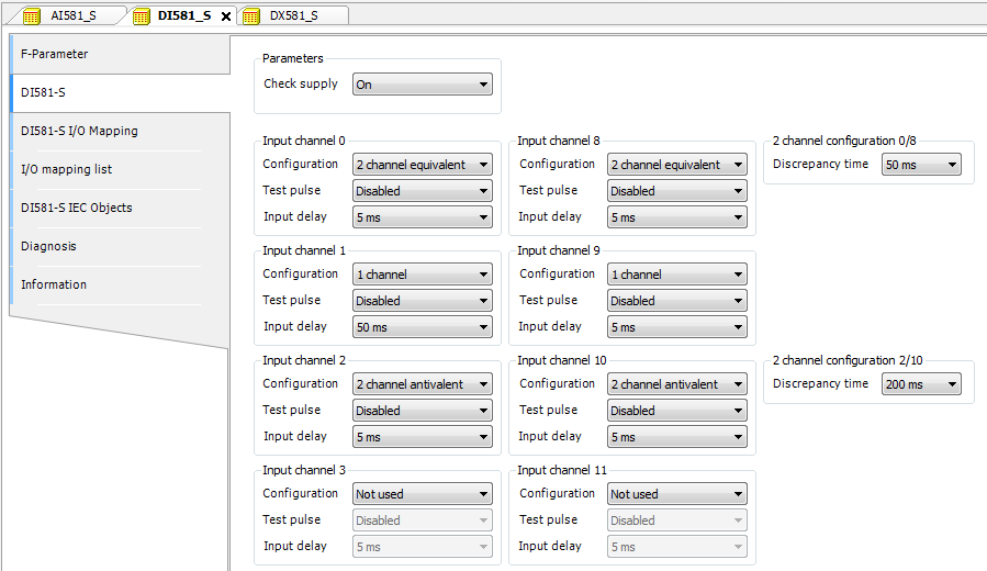
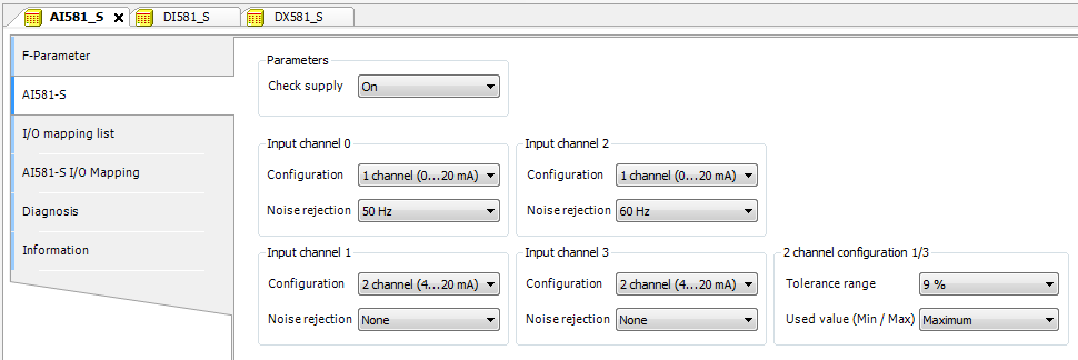
One can also use generic device configuration view from “DI581-S Parameters”, “DX581-S Parameters” or “AI581-S Parameters” tab to edit module and channel parameters. However, change of safety I/O parameters using generic device configuration view is not recommended due to potential user mistakes during the parameter setting using integer numbers.
Furthermore, each F-Device has a special “I/O Mapping” tab in which variable names for input and output signals, PROFIsafe diagnostic bits, etc. can be defined.
DANGER
If data types like Unsigned16, Unsigned32, Integer16, Integer32 or Float32, which require more than one byte, are used in PROFIsafe data, note the following. The byte order in such data types depends on the used PROFIsafe device endianness and selected AC500 non-safety CPU type. AC500 V2 non-safety CPU supports big-endian. AC500 V3 non-safety CPU supports little-endian. Make sure that the symbolic variables are mapped properly and the delivered safety data is correctly represented in your safety application.
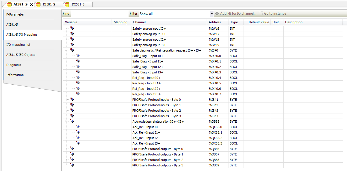
It is also valid for DX581-S and DI581-S safety modules; the only difference is the number of input and output channels. Each process channel (Input 0 - Input 3 for AI581-S) has additionally the following bits:
-
one bit for safe diagnostic (Safe_Diag bit) to be able to differentiate if the process value is the real process state or "0" value due to channel or module passivation.
-
one bit Rei_Req for channel reintegration request, which can be used in the safety application program as a signal that external error (e.g., sensor wiring error) was fixed and the channel can be reintegrated in the safety control. Higher overall system availability can be expected for end-customers, because they can selectively decide which channels have to be acknowledged and which not.
-
one bit Ack_Rei for channel reintegration if the error was fixed (e.g., external sensor wiring was corrected). One can also define one variable as a BYTE for all Ack_Rei bits and use 0xFF value to acknowledge all errors at once.
NOTICE
When you define variable names for input signal, output signal and other safety signals, pay attention to the safety programming guidelines.
NOTICE
Only BYTE data type is supported instead of WORD for safety data of DI581-S module when AC500 V3 non-safety CPU is used. It is needed to meet the endianness, which is different between AC500 V2 non-safety CPU (big-endian) and AC500 V3 non-safety CPU (little-endian). This shall be considered when safety project is migrated from AC500 V2 to V3 non-safety CPU.