


|
This is the web edition of the original ⮫ AC500-S safety user manual, version 1.3.2. This web edition is provided for quick reference only. The original safety user manual must be used to meet functional safety application requirements. |
INIT
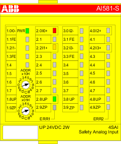
The hardware is initialized and internal start-up tests of the safety I/O module are executed. Refer to Fig.396 to see the LED states. After a successful parameterization, the PROFIsafe communication is expected to be initiated by the PROFIsafe F-Host.
The safety I/O module will remain in this state:
-
as long as the undervoltage is detected.
-
if the parameterization failed or pending.
-
if the PROFIsafe communication is pending.
Users have to check that a dedicated qualifier output bit (PROFIsafe diagnostic) for at least one of the channels in the given safety I/O module is set to "1" to verify that PROFIsafe F-Devices are initialized.
PROFIsafe status bits in the F-Host for safety I/O module:
OA_Req_S = 0
FV_activated_S = 1
Device_Fault = 0
Process data bits in the safety I/O module process image:
PROFIsafe diagnostic bit = 0
Channel process value = 0
Reintegration request bit = 0
RUN (ok)

PROFIsafe communication is up and running. The safety application is running without any detected errors.
PROFIsafe status bits in the F-Host for safety I/O module:
OA_Req_S = 0
FV_activated_S = 0
Device_Fault = 0
Process data bits in the safety I/O module process image:
PROFIsafe diagnostic bit = 1
Channel process value = Process value
Reintegration request bit = 0
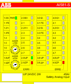
RUN (channel passivation and reintegration)
PROFIsafe communication is up and running. The safe application is running with detected channel errors.
Channel error (e.g., no expected test pulses, discrepancy time, etc.) is identified in at least one of channels. The fail-safe value ("0") is transferred to the PROFIsafe F-Host for the passivated input channel(s). The related PROFIsafe diagnostic bit(s) are also set to "0" to indicate the usage of fail-safe values.
A passivated output channel has a state of "0" and the related PROFIsafe diagnostic bit(s) are also set to "0" to indicate the usage of fail-safe values.
As soon as the channel error is gone (e.g., wiring error was corrected; this is valid only for those errors which are acknowledgeable), the reintegration request bit for the given channel switches to "1", which indicates the safety application running on the safety CPU that a reintegration of the channel is possible. Setting the acknowledge reintegration bit from "0" to "1" initiates a reintegration of the given channel. A positive edge from "0" to "1" is required to acknowledge channel reintegration.
As soon as all channel errors are gone and acknowledged, the RUN (ok) state is reached.
PROFIsafe status bits in the F-Host for safety I/O module:
OA_Req_S = 0
FV_activated_S = 0
Device_Fault = 0
Process data bits in the safety I/O module process image:
PROFIsafe diagnostic bit = 0
Channel process value = 0
Reintegration request bit = 0 if an error is still present; 1 if the channel can be reintegrated.
RUN (module passivation): alternating blinking of ERR1 and ERR2 LEDs
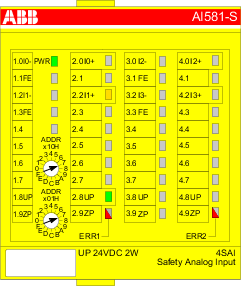
PROFIsafe communication is up and running. The safety application is running with a present module error.
The module and, as a result, all its channels are passivated. Possible reasons for module passivation are:
-
PROFIsafe communication failure (CRC error)
-
PROFIsafe watchdog timeout exceeded
-
Undervoltage/overvoltage detected (Device_Fault status bit = 1)
The fail-safe value "0" is transferred to the safety PLC for all passivated input channels, if the connection to the PROFIsafe F-Host is possible. The safety application continuously attempts to establish a communication to the safety CPU, if the communication is broken. All passivated output channels have a state of "0".
A state transition to another RUN mode is only possible if the detected error is gone.
PROFIsafe status bits in the F-Host for safety I/O module (if communication is possible!):
OA_Req_S = 0
FV_activated_S = 1
Device_Fault = 1 (in case of undervoltage/overvoltage detected) and/or CE_CRC = 1 (in case of communication error) and/or WD_timeout = 1 (in case of watchdog timeout)
Process data bits in the safety I/O module process image:
PROFIsafe diagnostic bit = 0
Channel process value = 0
Reintegration request bit = 0
RUN (module passivation with a command): alternating blinking of ERR1 & ERR2 LEDs
PROFIsafe communication is up and running. The safety application is running without any detected errors.
The module and all its channels are passivated because the safety application on the safety CPU requested a module passivation (activate_FV_C = 1 was set).
The fail-safe value "0" is transferred to the safety CPU for all passivated input channels. All passivated output channels have a state of "0". The PROFIsafe diagnostic bit(s) for all channels have the state of "0" to indicate that fail-safe values are transferred.
PROFIsafe status bits in the F-Host for safety I/O module:
FV_activated_S = 1
Process data bits in the safety I/O module process image:
PROFIsafe diagnostic bit = 0
Channel process value = 0
Reintegration request bit = 0
RUN (user acknowledgment request): alternating blinking of ERR1 & ERR2 LEDs
PROFIsafe communication is up and running. The safety application is running without any errors but waits for the acknowledgment of a module reintegration (module error is gone).
The fail-safe value "0" is still transferred to the safety CPU for all passivated input channels. All passivated output channels have a state of "0". The PROFIsafe diagnostic bits for all channels have the state of "0" to indicate that fail-safe values are transferred.
The OA_Req_S bit is reported as "1".
As soon as the safety application of the safety CPU sets OA_C (positive edge), the safety I/O module goes to RUN (ok) state if no further errors are detected. One has to send the positive edge to the safety I/O module until OA_Req_S starts delivering "0".
PROFIsafe status bits in the F-Host for safety I/O module:
OA_Req_S = 1
FV_activated_S = 1
Device_Fault = 0
Process data bits in the safety I/O module process image:
PROFIsafe diagnostic bit = 0
Channel process value = 0
Reintegration request bit = 0
SAFE STOP
The safety application execution was stopped. No PROFIsafe communication is possible.
This state is reached if an error of severity level 1 (e.g., CPU test, RAM test, etc. failed) took place.
This state can be left only through a power cycle or “reboot” command from non-safety CPU or communication interface module.
PROFIsafe status bits in the F-Host for safety I/O module:
OA_Req_S = 0
FV_activated_S = 1
Device_Fault = 0
Process data bits in the safety I/O module process image:
PROFIsafe diagnostic bit = 0
Channel process value = 0
Reintegration request bit = 0