


|
This is the web edition of the original ⮫ AC500-S safety user manual, version 1.3.2. This web edition is provided for quick reference only. The original safety user manual must be used to meet functional safety application requirements. |

DANGER
The diagnosis data is not safety-relevant and, thus, shall not be used in safety application program for execution of safety functions.
Fig. 400: LED states of safety I/O modules during start-up (example with AI581-S module)
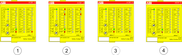
1
State 1 - Hardware reset and initialization
2
State 2 - LED test
3
State 3 - End state of initialization
4
State 4 - Parameterization is complete, but no PROFIsafe communication yet
Error messages

NOTICE
External errors (wiring or sensor errors) in safety I/O modules lead to the channel passivation ("0" values are delivered). As soon as an external error is fixed and this is recognized by internal safety I/O module tests, safety I/O module channels request an acknowledgment for their reintegration to the normal safety process control mode. The user can acknowledge such channels using dedicated channel bits(refer to Fig. 457).
Safety I/O module error messages are aggregated together with other module error messages in non-safety CPU.