


|
This is the web edition of the original ⮫ AC500-S safety user manual, version 1.3.2. This web edition is provided for quick reference only. The original safety user manual must be used to meet functional safety application requirements. |
Safety I/O module system states can be described using the following two state charts.
Fig. 398: Overview of transitions related to power cycles and errors of severity level 1 in safety I/O modules
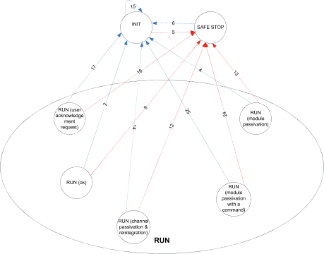

Power cycle

Error of severity level 1
Fig. 399: Overview of transitions in safety I/O modules (except power cycles and errors of severity level 1)
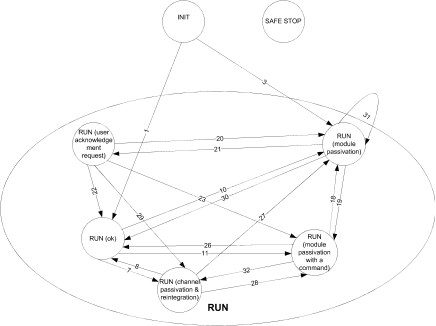

Transitions