


WARNING
Removal/Insertion under power
The option cards are not designed to be removed or inserted while the device is switched on. Due to unpredictable consequences, it is not permitted to connect or remove option cards while the device is powered on.
Make sure that all power sources (supply and process power) are switched off before you do the following:
-
Connection or disconnection of signals or terminal blocks.
-
Removal, installation or replacement of an option card.
Disconnecting a powered option card under voltage in a potentially explosive atmosphere may result in an electric arc, which could ignite combustible materials and cause a fire or explosion.
Make sure that the power supply is disconnected and the area has been toughly checked to ensure that no combustible materials are present before proceeding.
The option board TA5122-2AI-TC for analog input extension is plugged into a processor module PM50x2.
Insert the module and press it until it locks into place. A detailed description of the assembly and disassembly of the module can be found in the chapter Mounting and demounting option boards⮫ “Installation and removal of the option boards”.
The electrical connection is made via a removable 8-pin terminal block. For more information, please refer to the chapter TA52xx(-x) - Terminal block sets⮫ “TA5211, TA 5212 - Terminal block sets”. One terminal block is included in the scope of delivery of the module. Additional terminal blocks can be ordered separately as spare parts.
|
Terminal |
Signal |
Description |
|---|---|---|
|
1 |
I0+ |
Positive analog input I0 |
|
2 |
I0- |
Negative analog input I0 |
|
4 |
I1+ |
Positive analog input I1 |
|
5 |
I1- |
Negative analog input I1 |
|
7 |
UP |
Process voltage UP = +24 V DC |
|
8 |
ZP |
Process voltage ZP = 0 V |

NOTICE
Risk of damaging the PLC modules!
Overvoltages and short circuits might damage the PLC modules.
Make sure that all voltage sources (supply voltage and process supply voltage) are switched off before you begin with operations on the system.
Generally, analog signals must be laid in shielded cables. The cable shields must be grounded at both sides of the cables. To avoid unacceptable potential differences between different parts of the installation, low resistance equipotential bonding conductors must be laid.
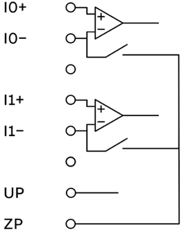
The following block diagram shows the internal construction of the analog inputs:
CAUTION
By installing equipotential bonding conductors between the different parts of the system, it must be ensured that the potential difference between ZP and AGND never can exceed 1 V.
CAUTION
The process supply voltage must be included in the grounding concept (e. g. grounding of the negative terminal ZP).
The module provides several diagnosis functions, see Diagnosis ⮫ Further information.
The meaning of the LEDs is described in the section State LEDs ⮫ Further information.
Grounded thermocouple
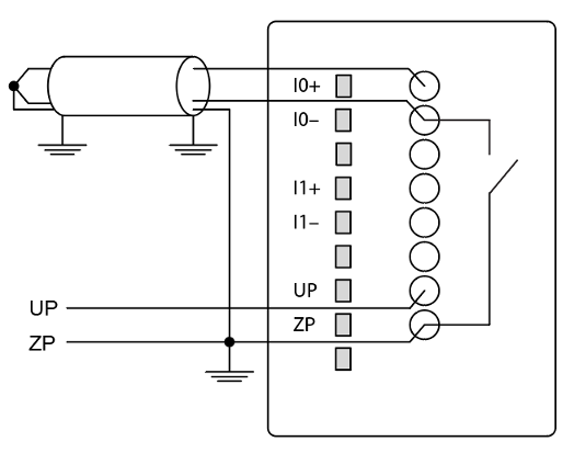
For grounded thermocouple the parameter “Thermocouple potential” should be set to “grounded”. In this configuration the terminal IO- can float internally from -1 V.. +1 V referenced to ZP.
CAUTION
It is necessary to pay attention that the thermocouple temperature measurement point is connected to ZP.
Isolated thermocouple
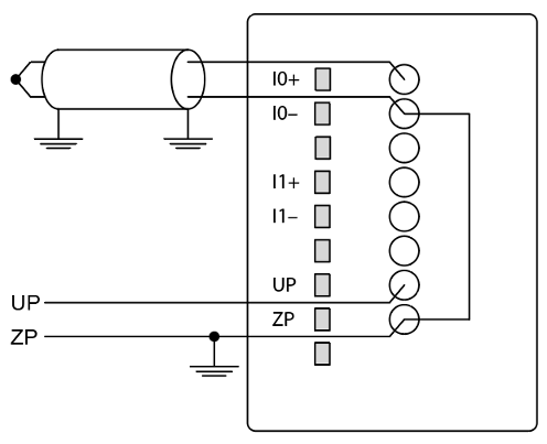
For isolated thermocouples the parameter “Thermocouple potential” should be set to “isolated”. In this configuration the terminal IO- will be grounded internally to ZP.
CAUTION
Carefully make sure that the entire thermocouple line, including the temperature measurement point, is isolated from any other potential.
The following measuring ranges can be configured:
|
B type |
0 °C...1820 °C |
Pt30Rh-Pt6Rh |
1 channel used |
|
E type |
-270 °C...1000 °C |
NiCr-CuNi |
1 channel used |
|
J type |
-210 °C...1200 °C |
Fe-CuNi |
1 channel used |
|
K type |
-270 °C...1372 °C |
Ni-CrNi |
1 channel used |
|
N type |
-270 °C...1300 °C |
NiCrSi-NiSi |
1 channel used |
|
R type |
-50 °C...1768 °C |
Pt13Rh-Pt |
1 channel used |
|
S type |
-50 °C...1768 °C |
Pt10Rh-Pt |
1 channel used |
|
T type |
-270 °C...400 °C |
Cu-CuNi |
1 channel used |
The module linearizes the characteristics of the thermocouple. It supports the following options for temperature compensation and cold junction handling:
-
Internal compensation
-
External compensation with temperature input
-
External compensation with compensation box