


WARNING
Removal/Insertion under power
The option cards are not designed to be removed or inserted while the device is switched on. Due to unpredictable consequences, it is not permitted to connect or remove option cards while the device is powered on.
Make sure that all power sources (supply and process power) are switched off before you do the following:
-
Connection or disconnection of signals or terminal blocks.
-
Removal, installation or replacement of an option card.
Disconnecting a powered option card under voltage in a potentially explosive atmosphere may result in an electric arc, which could ignite combustible materials and cause a fire or explosion.
Make sure that the power supply is disconnected and the area has been toughly checked to ensure that no combustible materials are present before proceeding.
The option board TA5120-2AI-UI for analog input extension is plugged into an AC500-eCo processor module PM50xx.
⮫ “Installation and removal of the option boards”
The electrical connection is made via a removable 6-pin terminal block.
The terminal block is included in the scope of delivery of the option board. Further terminal blocks can be ordered separately as spare parts.
⮫ “TA5211, TA 5212 - Terminal block sets”
|
Terminal |
Signal |
Description |
|---|---|---|
|
1 |
I0+ |
Positive analog input I0 |
|
2 |
I0- |
Negative analog input I0 |
|
3 |
I1+ |
Positive analog input I1 |
|
4 |
I1- |
Negative analog input I1 |
|
5 |
UP |
Process voltage UP = +24 V DC |
|
6 |
ZP |
Process voltage ZP = 0 V DC |
CAUTION
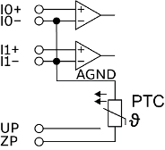
The negative terminal of the analog inputs are connected internally and form an internal analog ground (AGND). This analog ground is connected to ZP via a PTC resistor. There is no galvanic isolation between the analog circuitry and ZP/UP. Hence, analog inputs can not be connected in series.
The internal power supply of the circuits of the module takes place via the connection to the CPU. Thus, the current consumption from 24 V DC power supply at the terminals L+ and M of the CPU module increases by << 1 mA per TA5120-2AI-UI.
The external power supply is connected via the terminals UP (+24 V DC) and ZP (0 V DC).

NOTICE
Risk of damaging the PLC modules!
Overvoltages and short circuits might damage the PLC modules.
Make sure that all voltage sources (supply voltage and process supply voltage) are switched off before you begin with operations on the system.
Generally, analog signals must be laid in shielded cables. The cable shields must be grounded at both sides of the cables. To avoid unacceptable potential differences between different parts of the installation, low resistance equipotential bonding conductors must be laid.
The following figure shows the connection of the module:
CAUTION
By installing equipotential bonding conductors between the different parts of the system, it must be ensured that the potential difference between ZP and AGND never can exceed 1 V.
CAUTION
The process supply voltage must be included in the grounding concept (e. g. grounding of the negative terminal).
The option board provides several diagnosis functions.
Connection of active-type analog sensors (Voltage) with galvanically isolated power supply
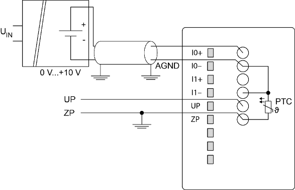
By connecting the sensor's negative terminal of the output voltage to AGND, the galvanically isolated voltage source of the sensor is referred to ZP.
|
Parameter |
Value |
|---|---|
|
Channel configuration |
0 V...+10 V |
In order to avoid error messages or long processing times, it is useful to configure unused analog input channels as "not used".
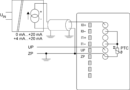
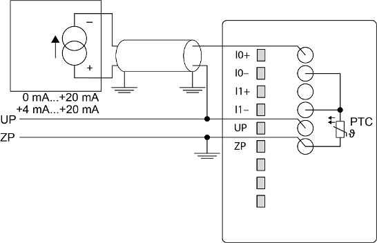
Connection of active-type analog sensors (Current) with galvanically isolated power supply
|
Parameter |
Value |
|---|---|
|
Channel configuration |
0 mA...+20 mA or +4 mA...+20 mA |
In order to avoid error messages or long processing times, it is useful to configure unused analog input channels as "not used".
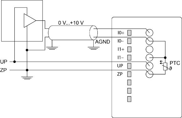
Connection of active-type analog sensors (Voltage) with no galvanically isolated power supply
CAUTION
The potential difference between AGND and ZP at the module must not be greater than 1 V, not even in case of long lines.
If AGND does not get connected to ZP, the sensor supply current flows to ZP via the AGND line. This current will distort the measuring signal, as a very small current flows through the AGND line. ZP connection should be close to the sensor. The total current through the PTC should not exceed 50 mA. This measuring method is therefore only suitable for short lines and small compensation currents via the AGND line.
|
Parameter |
Value |
|---|---|
|
Channel configuration |
0 V...+10 V |
In order to avoid error messages or long processing times, it is useful to configure unused analog input channels as "not used".
Connection of passive-type analog sensors (current)
|
Parameter |
Value |
|---|---|
|
Channel configuration |
0 mA...+20 mA or +4 mA...+20 mA |
In order to avoid error messages or long processing times, it is useful to configure unused analog input channels as "not used".
CAUTION
Risk of overloading the analog input!
If an analog current sensor supplies more than 25 mA for more than 1 second during initialization, this input is switched off by the module (input protection).
Only use sensors with fast initialization or without current peaks higher than 25 mA. If not possible, connect a 10-volt Zener diode in parallel to I+ and ZP.