


Configuring devices
You can configure the device objects inserted into the device tree in the associated device editor. The possibilities depend on the device description. The 'generic device editor' provides tabs that are supplemented as necessary by device-specific tabs.
Requirement: You have opened a standard project in whose device tree a standard PLC and below that a fieldbus device object are inserted.
-
Double-click the device object of the standard PLC in the device tree of your project.
The “<device name>” editor opens in the CODESYS main window. The “Communication Settings” tab is in the foreground. Change to the other tabs in order to make configuration settings for the controller. See the help pages for the generic device editor.
-
Double-click the fieldbus device object in the device tree of your project.
The “<fieldbus device name>” editor opens in the CODESYS main window. Specific tabs are available depending on the device. For the configuration options, see the help pages for the respective device editor. If the “Show generic device configuration views” option is selected in “Tools Options”, in the “Device Editor” category, then see also the tabs contributed by the generic device editor.
See also
General information about I/O mapping
Whether or not you can configure an I/O mapping to project variables or even to the entire function blocks depends on the type of device. Configuring an I/O map means linking input and output channels of the device with variables of the project. We also use the term 'mapping' for this.
Pay attention in general to the following for the mapping of inputs and outputs of a device to variables in CODESYS:
-
You do not have write access to variables that are mapped to an input.
-
You can map an existing variable to one input only.
-
You can directly generate new global implicit variables in the I/O map and map them to a device channel.
-
The memory layout of structures is specified by the device.
-
You can change addresses and fix values in the I/O map.
-
For each variable that is assigned to an I/O channel in the “I/O Mapping” dialog, you can cause 'force variables' to be generated during the compilation of the application (see further below). Using these variables you can, for example during the commissioning of a plant, force a value on the input or output via a visualization/HMI.
-
Changes in the I/O map can be transferred to the controller with an online change.
-
If a pointer to a device input is used, the access is considered to be a write access, for example
pTest := ADR(input);. This leads to a compiler warning when the code is generated: "...invalid assignment target". If you require a construct of this kind, you have to first copy the input valueinputto a variable with write access. -
An I/O address can also be linked with a variable via the 'AT declaration' in the IEC code. Since a device configuration often changes again, however, we recommend that you make the assignments only in the device editor.
If you use the AT declaration, note the following:
-
An AT declaration is permissible only with local or global variables, not with input or output variables of function blocks.
-
Implicit 'force variables' for I/Os (see below) cannot be generated for AT declarations.
-
If you use an AT declaration with structure variables or function block variables, all instances will access the same memory location. This then corresponds to the use of 'static variables' in classic programming languages such as 'C'.
-

NOTICE
If a pointer to a device input is used, then the access (for example, pTest := ADR(input);) applies as write access. This leads to a compiler warning when the code is generated:
"...invalid assignment target".
If you require a construct of this kind, you have to first copy the input value (input) to a variable with write access.
As an alternative, you can assign a variable to an address in the programming code using the AT declaration. In view of possible changes of the device configuration, however, we recommend that you make the assignments only in the device editor.
You can export the I/O mapping configuration of a device to a csv file or import it from such a file.
Linking a device input with an existing project variable ("mapping")
Requirement: A device that supports an I/O mapping configuration in CODESYS is inserted in the device tree of your project. On the “I/O Mapping” tab in the device editor you thus get a tabular display of the input and output channels of the device with specification of the addresses and data types.
NOTICE
Mapping 'too large' data types
If a variable of a data type that is larger than a byte is mapped to a byte address, the value of the variable will be truncated to byte size there. For monitoring the variable value in the “I/O Mapping” dialog, this means that, in the root element of the address, the value is displayed which the variable currently has in the project. The current individual bit values of the byte are displayed in succession in the bit elements below that, but this may not be sufficient for the entire variable value.
If a UNION is represented by I/O channels in the mapping dialog, it depends on the device whether mapping to the root element is also possible.
-
In a POU, declare, for example, a variable
xBool4of the typeBOOLwith which you want to access an input of the target device from the application. -
To open the device editor, double-click the device object in the device tree, and then the “<device name> I/O Mapping” tab.
-
Observe the “Variable” column with the display of the device input channels
 and device output channels
  , which can still be sorted by organizational nodes
  , depending on the device. We assume that there is a device input of the type
 BYTE. It is displayed with its individual bit addresses (bit channels) below theBYTEnode. -
Note: When mapping structured variables, the editor prevents you from entering both the structure variable (example:
%QB0) and individual structure elements (example:%QB0.1andQB0.2). Therefore, if there is a main entry with a subtree of bit channel entries in the mapping table, then the following applies: Then you can specify a variable either into the line of the main entry, or into the lines of the subelements (bit channels), but not into both.You can now occupy either the entire channel with a variable of a suitable type OR its individual bit-channel addresses with suitable variables of the type
BOOLorBIT. First of all, double-click a bit input channel in the “Variables” column.An input field opens.
-
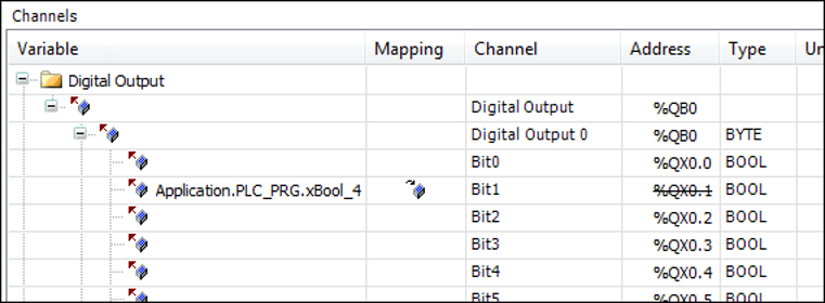
In order to place an existing variable on the channel, you have to enter the desired project variable with the complete path. Press
 to open the Input Assistant. Select, for example, the variable
 Application.PLC_PRG.xBool4declared inPLC_PRG.The variable is inserted. The HMI symbol (
 ) is displayed in the “ Mapping” column. The address is now struck through. That does not mean that the address is
no longer available, because values of existing variables are managed at another memory
space. But: in order to avoid ambiguities when writing the values, you should nevertheless
not occupy the address with a further variable, especially in the case of outputs.
) is displayed in the “ Mapping” column. The address is now struck through. That does not mean that the address is
no longer available, because values of existing variables are managed at another memory
space. But: in order to avoid ambiguities when writing the values, you should nevertheless
not occupy the address with a further variable, especially in the case of outputs.Note: For compiler version V3.5 SP11 and higher, the initialization value of the variables is used automatically as the default value when mapping to an existing variable. You can edit the “Default value” field only if you map to a new created variable or if no mapping is specified. In older versions, users had to specify explicitly that the default value and initialization value were identical.
-
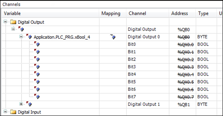
Delete the variable assignment again. Click the root of the channel, the
BYTEnode. Use the Input Assistant again to select the variableApplication.PLC_PRG.byte_gotodevice.The variable is inserted, all bit addresses of the main channel are struck through and you should not additionally occupy them.
See also
Mapping a device input to a recently created project variable
In the following you will map a device output to a global implicit variable, which you recently create for this purpose directly in the “I/O Mapping” dialog.
The “I/O Mapping” dialog is thus a further place for declaring a global variable.
Requirement: A device that supports an I/O mapping configuration in CODESYS is inserted in the device tree of your project. On the “I/O Mapping” tab in the device editor you will thus see a tabular display of the input and output channels of the device with specification of the addresses and data types.
-
To open the device editor, double-click the device object in the device tree, and then the “<device name> I/O Mapping” tab.
-
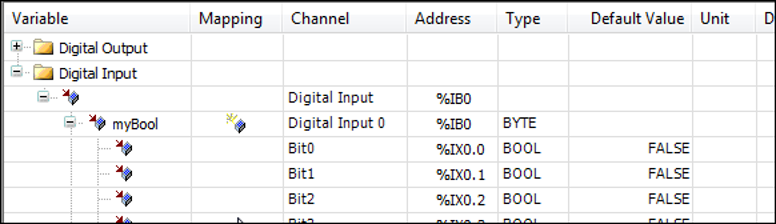
Click in the mapping table on a channel entry in the “Variable” column in order to open an input field.
-
Enter a simple name (without '
.') for a new variable (for example,myBool).CODESYS creates the variable as an implicit global variable in the project and assigns it directly to the channel address. Therefore in this case the address does not appear struck through as in the case of mappings to existing variables
 .
. 
Linking a device with a function block instance
If supported by the device, you can map entire function blocks to an input or output channel. This allows you to count the frequency of signal changes or scale a channel value for maintenance purposes, for example.
Here you will map a device output channel to a function block. In this example, the block scales the channel output value.
Requirement: A device with a digital output that supports FB mapping is linked in the project. There is a function block “Scale_Output_Int” with the following implementation. The attributes of the function block itself and before the output parameter with which the channel output is processed are important.
{attribute 'io_function_block'}
FUNCTION_BLOCK Scale_Output_Int
VAR_INPUT
	iInput : INT;
	iNumerator : INT;
	iDenominator : INT :=1;
	iOffset : INT := 0;
END_VAR
VAR_OUTPUT
 {attribute 'io_function_block_mapping'}
	iOutput : INT;
END_VAR
VAR
END_VAR
IF iDenominator <> 0 THEN
	iOutput := TO_INT(TO_DINT(iInput) * TO_DINT(iNumerator) / TO_DINT(iDenominator)) + iOffset;
-
Open the “<device name> I/O Mapping” tab of the device editor. Double-click the output that should be connected to the function block. Click the button
 “Add FB for IO channel”.
The “Select Function Block” dialog opens. On the left side, you see at least the function block “Scale_Output_int” below the “Application” node. Libraries linked in the project that contain corresponding function blocks are also displayed for selection.
-
Select the POU
myScaleOutputInt.After clicking “OK”, the path of the function block parameter
iOutputin the “Variable” is entered in the mapping dialog. The path comprises the application name, the device channel name, and the selected FB output (example:App1.Out_4_Int_myScale_Output_Int_1.iOutput). -
Select the channel and click
 “Go to Instance”.
The focus switches to the “<device name> IEC Objects” tab and the created entry for the new IEC object
Out_4_Int_myScale_Output_Int_1. In this view in online mode, you see the current value of the parameteriOutputfor the channelOut_4_Intscaled by the FB. You can also write and force the value as in other monitoring views.
Changing and fixing an address value in the I/O map
You can change the address value of an entire channel (but not that of an individual subelement of the channel!) in the mapping table of the “<device name> I/O Mapping” tab. This allows you to adapt the addressing to a specified machine configuration and to retain the address value even if the layout of the modules changes. By default, a change of the layout leads to an automatic adaptation of the address values.
Requirement: Your project has I/O mapping. See the corresponding sections of the help page above.
-
To open the device editor, double-click the device object in the device tree, and then the “<device name> I/O Mapping” tab.
-
Click in the mapping table on a channel entry in the “Address” column in order to open an input field. This is only possible for the 'root' address of a channel, not for a particular one of its subelements.
Therefore, change the top address entry of a channel in the table, for example from
QB0toQB1. Exit the input field.The address value is changed. The symbol
 is displayed before the address. It indicates that the address is fixed. The addresses
of the subelements of the channel are also changed accordingly. If you now change
the position of the device object inside other device objects with input/output channels
in the device tree, CODESYS does not adapt these addresses to the new order as would be the case without fixing.
is displayed before the address. It indicates that the address is fixed. The addresses
of the subelements of the channel are also changed accordingly. If you now change
the position of the device object inside other device objects with input/output channels
in the device tree, CODESYS does not adapt these addresses to the new order as would be the case without fixing.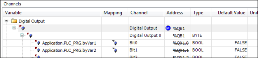
-
In order to undo the manual change or fixing, open the input field of the address value again, delete the address entry and press the Enter key.
CODESYS resets the address and the subsequent addresses concerned to the values they had before the change and removes the symbol
.
Configuration of the I/O variable update
Depending on the device that you link in the project, CODESYS updates the variables applied to its inputs and outputs in different ways. You can explicitly change the settings for this in the “I/O Mapping” dialog.
See also
Monitoring of variables in the I/O map in online mode
Requirement: You have compiled an application with a device configuration containing I/O maps without error. The associated hardware and the bus system are running. You have connected to the controller by means of the “Online Login” command and have loaded and started the application.
-
Open the “I/O Mapping” tab of the PLC in the device editor. To open the editor, double-click the device object in the device tree.
The mapping table now additionally contains the “Current Value” and “New Value” columns.
If a structure variable is mapped to the 'root' element of an address1, CODESYS does not display a value in this line in online mode. If, for example, a
DWORDvariable is mapped to the address, however, the respective values are monitored both in the 'root' line and in the indented bit-channel lines below it.As a matter of principle, the field in the 'root' line always remains empty if the value would be composed of several subelements.
1 'root' = top element of this address in the Mapping dialog
-
Enter a certain variable value for an entry in the column “New value” and press [F7] to force or [Ctrl]+[F7] to write the value.
As in the case of monitoring in the declaration editor or in watch lists, the forced variable value is displayed in the column “Current Value” with a prefixed red F-symbol or the written value.
NOTICE
Inputs and outputs that the PLC code does NOT use are not read by the PLC in online mode, as a result of which the displayed value could be incorrect. The “Current Value” of the variables concerned is displayed with a gray background.
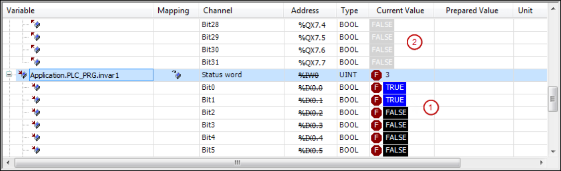
- (1)
-
Forced values on the controller
- (2)
-
Values not used on the controller, value shown in gray
Generating implicit variables for the forcing of I/Os
During the commissioning of a plant or machine it may be necessary to 'force' the values applied at the inputs and outputs. If a device supports this you can cause special 'force variables' to be generated for this purpose and use them, for example, in an HMI visualization.
Requirement: The device supports the functionality. You have a project in which an
I/O map is configured for the device and which contains a program object PLC_PRG.
-
Open the device editor, “PLC Settings” tab, by double-clicking the device object in the device tree.
-
Activate the option “Generate force variables for IO mapping”.
-
Press [F11] to compile the application.
Two variables are created for each I/O channel in accordance with the following syntax, in the process of which spaces in the channel name are replaced by underscores:
<device name>_<channel name>_<IEC address>_Forceof typeBOOLfor the activation and deactivation of forces.<device name>_<channel name>_<IEC address>_Valueof the data type of the channel for defining the value that you want to force on the channel.These variables are available in the Input Assistant in the category “Variables” / “IoConfig_Globals_Force_Variables.” You can use them in CODESYS in programming objects, in visualizations, in the symbol configuration, etc.
-
Open the function block “PLC_PRG”, set the focus in the implementation part and press F2.
The Input Assistant opens. The variables are available in the category “Variables” / “IoConfig_Globals_Force_Variables” as described above.
A rising edge at the 'Force variable' input activates the forcing of the respective input or output with the value given by the 'Value variable'. A falling edge deactivates the forcing. Deactivation by resetting the 'Force' variable to
FALSEis the requirement for being able to force a new value.
Take note of the following restrictions.
-
Forcing via the implicit force variables is only possible for channels that are mapped in the “I/O Mapping” of the device to an existing or recently created variable.
-
Forcing via the implicit force variables is not possible for unused inputs and outputs or those that are mapped to a variable via an AT declaration in an application program.
-
I/O channels that you want to force via the mechanism have to be used by CODESYS in at least one task.
-
CODESYS identifies forced inputs in the monitoring by the red Force symbol, but not forced input/outputs. The forced value is used only implicitly by the I/O driver for writing to the device.
I/O mapping in one dialog for multiple devices
There is a table that displays the I/O map of a device plus the I/O maps of all subelements inserted below it in the device tree. There you can edit the I/O maps in exactly the same way as in the individual mapping tables of the respective device editors.
Requirement: In the device tree of your project there are several PLCs inserted that each enable an I/O mapping configuration.
-
Select the root node of the device tree and click “Edit I/O Mapping” in the context menu .
The “Edit I/O Mapping” dialog opens, in which the I/O mapping configurations of all devices inserted in the project are displayed in a table. You can edit the entries in the same way as in the “I/O Mapping” dialog of the associated device editor.
-
Now select one of the control objects in the device tree and select the “Edit I/O Mapping” command once again in the context menu.
The “Edit I/O Mapping” dialog now shows only the I/O table for the I/O mapping configurations found in and under the selected object.
-
Set a desired “Filter” in the bar above the table or enter a variable name in the “Search for variable” field in order to see the use of this variable in the mapping.
The method of working in this window is the same as that described for the “<device name> I/O Mapping” tab.
See also