


Devices with I/O channels
This tab is displayed in device editors for devices with I/O channels. It shows the available channels and allows for the mapping of input, output, and memory addresses of the controller to variables or entire function blocks of the application. In this way, you create the 'I/O Mapping'.
The application that is to take care of the I/O handling is defined on the “PLC Settings” tab.
You can use the "Online Configuration Mode" if the device supports it. In this mode, you can access the I/Os of the hardware without having to download an actual application to the device beforehand.
You can also create the I/O mapping in the “Edit I/O Mapping” dialog. Here you get a mapping list with search and filter functions for an entire device tree.

NOTICE
Mapping 'too large' data types
If a variable of a data type that is larger than a byte is mapped to a byte address, the value of the variable will be truncated to byte size there. For monitoring the variable value in the “I/O Mapping” dialog, this means that, in the root element of the address, the value is displayed which the variable currently has in the project. The current individual bit values of the byte are displayed in succession in the bit elements below that, but this may not be sufficient for the entire variable value.
Example of the “<device name> I/O Mapping” tab for a CAN bus slave:
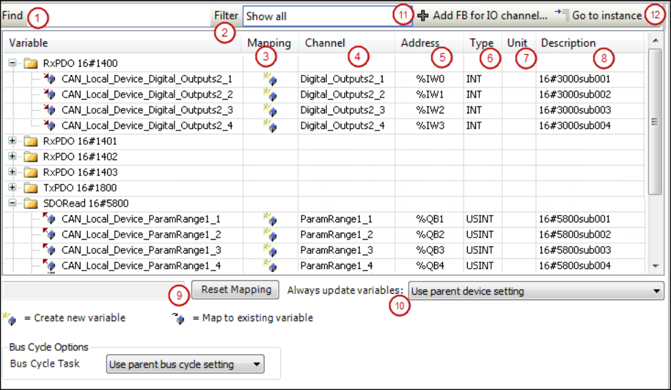
The tab contains a table for editing the I/O mapping. The information displayed for the inputs and outputs originates from the device description.
|
“Find” (1) |
Input field for a search string for the mapping table. The search results are marked in yellow. |
|
“Filter” (2) |
List box with filters for the I/O mappings displayed in the mapping table:
|
|
|
Depending on the device, available if the channel entry is selected in the mapping table. Opens the “Select Function Block” dialog for selecting the function block that should be linked directly to the channel. |
|
|
Available if the entry is selected in the mapping table. Jumps to the corresponding entry on the “<device name> IEC Objects” tab. |
|
“Variable” |
Depending on the device, the inputs and outputs of the device are displayed as nodes and below them, indented, the associated channels or, depending on the device, only the implicitly created device instance. The symbol indicates the type of channel:
Double-click the cell to open an input field.
Depending on the device, inputs or outputs can be linked directly to a function block.
In this case, the |
|
“Mapping” (3) |
Type of mapping:
|
|
“ Channel” (4) |
Symbolic name of the channel. |
|
“Address” (5) |
Address of the channel (example: Address strikethrough: Indicates that you should not assign any more variables to this address. Reason: Although the variable specified here is managed – as an existing variable –at a different memory location, ambiguity could result when the values are written, particularly with outputs.
|
|
“Type” (6) |
Data type of the channel (example: Structures or bit fields defined in the device description are displayed only if they are part of the IEC standard and are identified as IEC data types in the device description. Otherwise the table cell remains empty. When mapping structured variables, the editor prevents you from specifying both the
structure variable (example: |
|
“Default value” |
Default value of the parameter that applies to the channel: Appears only if the option “Set all outputs to default” is selected in the “PLC Settings” for the behavior of the outputs at stop. Note: For compiler version V3.5 SP11 and higher, the initialization value of the variables is used automatically as the default value when mapping to an existing variable. You can edit the “Default value” field only if you map to a new created variable or if no mapping is specified. In older versions, users had to specify explicitly that the default value and initialization value were identical. |
|
“Unit” (7) |
Unit for the parameter value (example: |
|
“Description” (8) |
Short description of the parameter. |
|
“Current value” |
Actual value of the parameter applied to the channel; displayed in online mode only. |


 : Input
 : Output
 .
. : Existing variable
 : New variable
 : Mapping to function block instance
 : Indicates that this address has been edited and fixed. If the arrangement of the
device objects in the device tree changes, then
: Indicates that this address has been edited and fixed. If the arrangement of the
device objects in the device tree changes, then The change of the default value by an online change is allowed, however the value is applied only after a "Reset cold" or "Reset warm".
|
“Reset Mapping” (9) |
CODESYS resets the mapping settings to the default values as defined in the device description file. |
|
“Always update variables” (10) |
Definition for the device object about updating I/O variables. The default value is defined in the device description:
|
If a UNION is represented by I/O channels in the mapping dialog, it depends on the device whether mapping to the root element is also possible.
Devices with I/O drivers
For devices with I/O drivers, you can set the bus cycle task here in the “I/O Mapping” tab if the general settings should not be used (“PLC Settings” tab).
|
“Bus Cycle Task ” |
The list box provides all tasks which are defined in the task configuration of the active application (example: “MainTask”. In case of “Use parent bus cycle setting”, the settings of the parent node will be used. |
General information about the bus cycle task
Generally, for each IEC task, the used input data is read at the start of each task (1) and the written output data is transferred to the I/O driver at the end of the task (3). The implementation in the I/O driver is decisive for additional transfer of the I/O data. It is responsible for the time frame and time point that the actual transfer to the corresponding bus system occurs.
The bus cycle task of the PLC can be defined globally for all fieldbuses in the PLC settings. For some fieldbuses, however, you can change this independent of the global setting. The task with the shortest cycle time is used as the bus cycle task (setting: “unspecified” in the PLC settings). The messages are normally sent on the bus in this task.
Other tasks copy only the I/O data from an internal buffer that is exchanged only with the physical hardware in the bus cycle task.
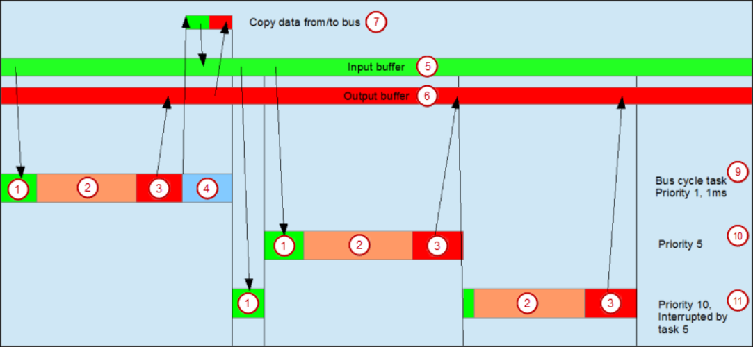
(1) Read inputs from input buffer             (2) IEC task
(3) Write outputs to output buffer      (4) Bus cycle
(5) Input buffer                                    (6) Output buffer
(7) Copy data to/from bus
(9) Bus cycle task, priority 1, 1 ms
(10) Bus cycle task, priority 5
(11) Bus cycle task, priority 10, interrupted by task 5
Task usage
The “Task Deployment” tab provides an overview of used I/O channels, the set bus cycle task, and the usage of channels.

WARNING
If an output is written in various tasks, then the status is undefined, as this can be overwritten in each case.
If the same inputs are used in various tasks, then it is possible for the input to change during the processing of a task. This happens when the task is interrupted by a task with a higher priority and causes the process image to be read again. Solution: At the beginning of the IEC task, copy the input variables to variables and then work only with the local variables in the rest of the code.
Conclusion: Using the same inputs and outputs in several tasks does not make any sense and can lead to unexpected reactions in some cases.