


WARNING
Risk of death by electric shock!
Hazardous voltages can be present at the terminals of the module.
Make sure that all voltage sources (supply voltage and process supply voltage) are switched off before you begin with operations on the system.
For a detailed description of the mounting, disassembly and connection of the module, please refer to the ⮫ installation instructions.
The connection of the I/O channels is carried out using the 40 terminals of the I/O terminal unit. I/O modules can be replaced without re-wiring the terminal units.
The terminals 1.8 ... 4.8 and 1.9 ... 4.9 are electrically interconnected within the I/O terminal unit.
The terminals always have the same assignment, irrespective of the inserted module:
-
Terminals 1.8 ... 4.8: process supply voltage UP = +24 V DC
-
Terminals 1.9 ... 4.9: process supply voltage ZP = 0 V DC
|
Terminals |
Signal |
Description |
|---|---|---|
|
1.0 ... 1.7 |
unused |
|
|
2.0 and 3.0 |
I0 and I1 |
Input signals for the digital inputs I0 and I1 |
|
4.0 |
N01 |
Neutral conductor for the digital inputs I0 and I1 |
|
2.1 and 3.1 |
I2 and I3 |
Input signals for the digital inputs I2 and I3 |
|
4.1 |
N23 |
Neutral conductor for the digital inputs I2 and I3 |
|
2.2 and 3.2 |
I4 and I5 |
Input signals for the digital inputs I4 and I5 |
|
4.2 |
N45 |
Neutral conductor for the digital inputs I4 and I5 |
|
2.3 and 3.3 |
I6 and I7 |
Input signals for the digital inputs I6 and I7 |
|
4.3 |
N67 |
Neutral conductor for the digital inputs I6 and I7 |
|
2.4 |
R0 |
Common contact of the first relay output |
|
3.4 and 4.4 |
NO0 and NC0 |
NO and NC contacts of the first relay output |
|
2.5 |
R1 |
Common contact of the second relay output |
|
3.5 and 4.5 |
NO1 and NC1 |
NO and NC contacts of the second relay output |
|
2.6 |
R2 |
Common contact of the third relay output |
|
3.6 and 4.6 |
NO2 and NC2 |
NO and NC contacts of the third relay output |
|
2.7 |
R3 |
Common contact of the fourth relay output |
|
3.7 and 4.7 |
NO3 and NC3 |
NO and NC contacts of the fourth relay output |
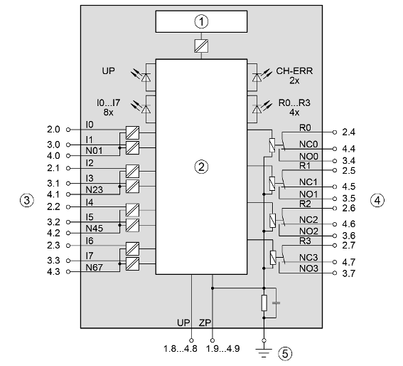
1
I/O bus interface
2
Logic
3
Digital inputs
4
Relay output
5
Functional earth connection
The internal power supply voltage for the module's circuitry is carried out via the I/O bus (provided by a communication interface module or a CPU). Thus, the current consumption from 24 V DC power supply at the terminals L+/UP and M/ZP of the CPU/communication interface module increases by 2 mA per DX531. The external power supply connection is carried out via the UP (+24 V DC) and the ZP (0 V DC) terminals.
WARNING
Removal/Insertion under power
Removal or insertion under power is permissible only if all conditions for hot swapping are fullfilled.
⮫ “Replace an I/O module with hot swap”
The devices are not designed for removal or insertion under power when the conditions for hot swap do not apply. Because of unforeseeable consequences, it is not allowed to plug in or unplug devices with the power being ON.
Make sure that all voltage sources (supply and process voltage) are switched off before doing any of the following actions:
-
Connect or disconnect any signal or terminal block.
-
Remove, mount or replace a module.
Disconnecting any powered devices while they are energized in a hazardous location could result in an electric arc, which could create an ignition source resulting in fire or explosion.
Prior to proceeding, make sure that power is been disconnected and that the area has been thoroughly checked to ensure that flammable materials are not present.
The devices must not be opened when in operation. The same applies to the network interfaces.

NOTICE
Risk of damaging the PLC modules!
Overvoltages and short circuits might damage the PLC modules.
-
Make sure that all voltage sources (supply voltage and process supply voltage) are switched off before you begin with operations on the system.
-
Never connect any voltages or signals to reserved terminals (marked with ---). Reserved terminals may carry internal voltages.
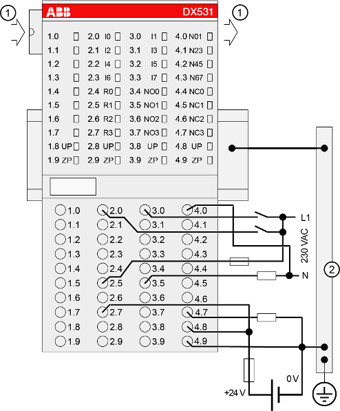
1
I/O bus
2
Control cabinet earth
NOTICE
-
If the relay outputs have to switch inductive DC loads, free-wheeling diodes must be circuited in parallel to these loads.
-
If the relay outputs have to switch inductive AC loads, spark suppressors are required.
CAUTION
The process supply voltage must be included in the grounding concept (e. g. grounding of the negative terminal).
NOTICE
Risk of damaging the PLC module!
The following has to be considered when connecting input and output voltages to the module:
-
All 230 V AC feeds must be single phase from the same supply system.
-
Connection of 2 or more relay contacts in series is possible; however, voltages above 230 V AC and 3-phase loads are not allowed.
-
The 4 change-over contacts of the relays are galvanically isolated from channel to channel. This allows to connect loads of 24 V DC and 120/230 V AC to relay outputs of the same module. In such cases it is necessary that both supply voltages are grounded to prevent unsafe floating grounds.
-
All input signals must come from the same phase of the same supply system (together with the used neutral conductor). The module is designed for 120/230 V AC max., not for 400 V AC, not even between two input terminals.
-
All neutral conductor connections must be common to the same supply system, since the terminals 4.0 ... 4.3 are interconnected within the module. Otherwise, accidental energization could occur.
NOTICE
Risk of damaging the PLC module!
There is no internal short-circuit or overload protection for the relay outputs.
Protect the relay contacts by back-up fuses of 6 A max. (characteristic gG/gL). Depending on the application, fuses can be used for single channels or module-wise.
The module provides several diagnosis functions.