


|
This is the web edition of the original ⮫ AC500-S safety user manual, version 1.3.2. This web edition is provided for quick reference only. The original safety user manual must be used to meet functional safety application requirements. |
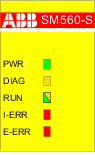
Safety CPU status is shown by its LEDs. RUN LED is bicolored. The following figure and table show positions and functions of 5 LEDs.
Fig. 394: LEDs for status display
|
LED |
Description |
Color |
Status |
Meaning |
|---|---|---|---|---|
|
PWR |
Module power supply |
Green |
ON |
+3.3V internal power supply is available |
|
BLINKING |
Not applicable |
|||
|
OFF |
+3.3V internal power supply is not available |
|||
|
DIAG |
Diagnostics |
Yellow |
ON |
Configuration error |
|
BLINKING |
Not applicable |
|||
|
OFF |
No configuration error |
|||
|
RUN |
Run mode indicator |
Green |
ON |
Safety CPU is in RUN (safety) mode. The application program is executed. |
|
BLINKING |
Not applicable |
|||
|
OFF |
Safety CPU is in DEBUG STOP (non-safety) mode. The application program is not executed. |
|||
|
Yellow |
ON |
Safety CPU is in DEBUG RUN (non-safety) mode. The application program is executed. |
||
|
BLINKING |
Firmware, boot project or boot code update indication |
|||
|
OFF |
Safety CPU is in DEBUG STOP (non-safety) mode. The application program is not executed. |
|||
|
I-ERR |
Internal device error indicator |
Red |
ON |
Internal device error leading to a SAFE STOP state (no valid PROFIsafe telegrams are generated by the device). |
|
BLINKING |
Firmware or boot code update |
|||
|
OFF |
No internal device error leading to a safe state |
|||
|
E-ERR |
External error indicator |
Red |
ON |
This LED can be set only from the user application program using a special library POU SF_E_ERR_LED_SET⮫ “SF_E_ERR_LED_SET”. One of possible use cases is the visualization of important external device errors. |
|
BLINKING |
This LED can be set only from the user application program using a special library POU SF_E_ERR_LED_SET⮫ “SF_E_ERR_LED_SET”. One of possible use cases is the visualization of light external device errors. |
|||
|
OFF |
No external errors were identified. |
Fig. 395: LED states of the safety CPU during start-up

1
State 1 - Hardware reset
2
State 2 - Initialization
3
State 3 - LED test
4
State 4 - End of start-up
Error messages
Safety CPU error messages are aggregated together with other communication module error messages in the non-safety CPU. All error messages can be observed on the non-safety CPU. In addition, error messages of the safety CPU can be observed on the safety CPU itself.
⮫ Error messages for safety CPU
⮫ Complete list of error messages for AC500 V3

NOTICE
The error messages of not only the safety CPU but also of safety I/O modules are visualized on non-safety CPU display.
No error message overflow on the safety CPU is possible. The maximum number of entries in the safety CPU diagnosis system is 100. If all 100 entries in the diagnosis system are occupied, the newest entry overwrites the oldest one.
After a power cycle of the safety CPU, error messages are deleted from the safety CPU diagnosis system.