


|
This is the web edition of the original ⮫ AC500-S safety user manual, version 1.3.2. This web edition is provided for quick reference only. The original safety user manual must be used to meet functional safety application requirements. |
|
Standards |
Requirements |
|---|---|
|
IEC 61496-1:2012 |
A.7 Muting A.7.1.2 There shall be at least two independent hard-wired muting signal sources to initiate the function. It shall not be possible to initiate muting when the OSSDs are already in the OFF-state. A.7.1.3 The mute function shall only be initiated by the correct sequence and/or timing of the mute signals. Should conflicting muting signals occur, the ESPE shall not allow a muted condition to occur. A.7.1.4 There shall be at least two independent hard-wired muting signal sources to stop the function. The muting function shall stop when the first of these muting signals changes state. The deactivation of the muting function shall not rely only on the clearance of the ESPE. A.7.1.5 The muting signals should be continuously present during muting. When the signals are not continuously present, an incorrect sequence and/or the expiration of a pre-set time limit shall cause either a lock-out condition or a restart interlock. A.7.4 Indication: A mute status signal or indicator shall be provided (in some applications, an indication signal of muting is necessary) |
|
IEC / TS 62046/Ed. 2:2008 |
5.5. General application requirements for muting |
|
ISO 13849-1:2015 |
5.2.2 Manual reset function |
|
ISO 12100: 2010 |
6.2.11.4: Restart following power failure/spontaneous restart |
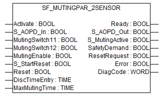
Muting is the intended suppression of the safety function. In this FB, parallel muting with two muting sensors is specified.
This is required, e.g., when transporting the material into the danger zone without causing the machine to stop. Muting is triggered by muting sensors. The use of two muting sensors and correct integration into the production sequence must ensure that no persons enter the danger zone while the light curtain is muted. Muting sensors can be push buttons, proximity switches, photoelectric barriers, limit switches, etc. which do not have to be fail-safe. Active muting mode must be indicated by indicator lights.
There are sequential and parallel muting procedures. In this FB, parallel muting with two muting sensors was used; an explanation is provided below. The positioning of the sensors should be as described in Annex F.7 of IEC 62046, 2005⮫ “Example for SF_MutingPar_2Sensor with two reflecting light barriers”. The FB can be used in both directions, forward and backward. However, the actual direction cannot be identified. The muting should be enabled with the MutingEnable signal by the process control to avoid manipulation.
The FB input parameters include the signals of the two muting sensors (MutingSwitch11 and MutingSwitch12), the OSSD signal from the AOPD device (S_AOPD_In) as well as two parameterizable times (DiscTimeEntry and MaxMutingTime).
The S_StartReset input shall only be activated if it is ensured that no hazardous situation can occur when the PES is started.
|
Name |
Data type |
Initial value |
Description, parameter values |
|---|---|---|---|
|
VAR_INPUT |
|||
|
Activate |
BOOL |
FALSE |
|
|
S_AOPD_In |
BOOL |
FALSE |
Variable. OSSD signal from AOPD. FALSE: Protection field interrupted. TRUE: Protection field not interrupted. |
|
MutingSwitch11 |
BOOL |
FALSE |
Variable. Status of Muting sensor 11. FALSE: Muting sensor 11 not actuated. TRUE: Workpiece actuates muting sensor 11. |
|
MutingSwitch12 |
BOOL |
FALSE |
Variable. Status of Muting sensor 12. FALSE: Muting sensor 12 not actuated. TRUE: Workpiece actuates muting sensor 12. |
|
MutingEnable |
BOOL |
FALSE |
Variable or constant. Command by the control system that enables the start of the muting function when needed by the machine cycle. After the start of the muting function, this signal can be switched off. FALSE: Muting not enabled. TRUE: Start of Muting function enabled. |
|
S_StartReset |
BOOL |
FALSE |
|
|
Reset |
BOOL |
FALSE |
|
|
DiscTimeEntry |
TIME |
T#0s |
Constant 0..4 s; Max. discrepancy time for MutingSwitch11 and MutingSwitch12 entering muting gate |
|
MaxMutingTime |
TIME |
T#0s |
Constant 0..120 min; Maximum time for complete muting sequence, timer starts with the first actuated muting sensor. |
|
VAR_OUTPUT |
|||
|
Ready |
BOOL |
FALSE |
|
|
S_AOPD_Out |
BOOL |
FALSE |
Safety related output, indicates status of the muted guard. FALSE: AOPD protection field interrupted and muting not active. TRUE: AOPD protection field not interrupted or muting active. |
|
S_MutingActive |
BOOL |
FALSE |
Indicates status of Muting process. FALSE: Muting not active. TRUE: Muting active. |
|
SafetyDemand |
BOOL |
FALSE |
Optional. |
|
ResetRequest |
BOOL |
FALSE |
Optional. |
|
Error |
BOOL |
FALSE |
|
|
DiagCode |
WORD |
16#0000 |
|
Example for SF_MutingPar_2Sensor with two reflecting light barriers
Fig. 498: Example for SF_MutingPar_2Sensor
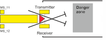
If reflection light barriers are used as muting sensors, they are generally arranged diagonally. In general, this arrangement of reflection light barriers as muting sensors requires only two light barriers, and only MutingSwitch11 (MS_11) and MutingSwitch12 (MS_12) are allocated.
Muting conditions
Muting condition 1 (to 8010) (MS_11 is the first entry switch actuated). Start timer DiscTimeEntry and MaxMutingTime: MutingEnable AND R_TRIG at MS_11 AND NOT MS_12
Muting condition 2 (to 8310) (MS_12 is the first entry switch actuated). Start timer DiscTimeEntry and MaxMutingTime: MutingEnable AND NOT MS_11 AND R_TRIG at MS_12
Muting condition 3 (from 8010 to 8020) (MS_12 is the second entry switch actuated): Stop timer DiscTimeEntry: MutingEnable AND MS_11 AND R_TRIG at MS_12
Muting condition 4 (from 8310 to 8020) (MS_11 is the second entry switch actuated): Stop timer DiscTimeEntry: MutingEnable AND R_TRIG at MS_11 AND MS_12
Muting condition 5 (from 8000 to 8020) (both switches actuated in same cycle): Start Timer MaxMutingTime: MutingEnable AND R_TRIG at MS_11 AND R_TRIG at MS_12
Muting condition 6 (from 8020 to 8000) (both switches released in same cycle or MS_11 and MS_12 released consecutively). Stop timer MaxMutingTime: NOT MS_11 OR NOT MS_12
Wrong muting sequences
- State 8000
-
(R_TRIG at MS_11 AND MS_12 AND NOT R_TRIG at MS_12) OR
(R_TRIG at MS_12 AND MS_11 AND NOT R_TRIG at MS_11) OR
((MS_11 AND NOT R_TRIG at MS_11) AND (MS_12 AND NOT R_TRIG at MS_12)) OR
(NOT MutingEnable AND R_TRIG at MS_11) OR
(NOT MutingEnable AND R_TRIG at MS_12)
- State 8010
-
NOT MutingEnable OR NOT MS_11
- State 8310
-
NOT MutingEnable OR NOT MS_12
- State 8020
-
No case of wrong muting sequences in this state.
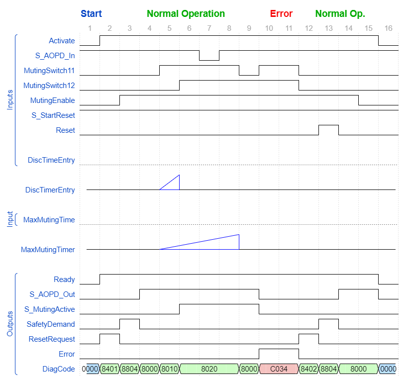
Typical timing diagram
Fig. 499: Typical timing diagram for SF_MutingPar_2Sensor
Error detection
The FB detects the following error conditions:
-
DiscTimeEntry has been set to value less than T#0s or greater than T#4s.
-
MaxMutingTime has been set to a value less than T#0s or greater than T#120min.
-
The discrepancy time for the MutingSwitch11/MutingSwitch12 sensor pair has been exceeded.
-
The muting function (S_MutingActive = TRUE) exceeds the maximum muting time MaxMutingTime.
-
Muting sensors MutingSwitch11, MutingSwitch12 are activated in the wrong order.
-
Muting sequence starts without being enabled by MutingEnable.
-
Static muting sensor signals.
-
A static Reset condition is detected in state 8401 and 8402.
Error behavior
In the event of an error, the S_AOPD_Out and S_MutingActive outputs are set to FALSE. The DiagCode output indicates the relevant error code and the Error output is set to TRUE.
A restart is inhibited until the error conditions are cleared and the safe state is acknowledged with Reset by the operator.
Function block-specific error and status codes
|
DiagCode |
State name |
State description and output setting |
|---|---|---|
|
C001 |
Reset Error 1 |
Static Reset condition detected after FB activation in state 8401. Ready = TRUE S_AOPD_Out = FALSE S_MutingActive = FALSE SafetyDemand = FALSE ResetRequest = FALSE Error = TRUE |
|
C011 |
Reset Error 2 |
Static Reset condition detected in state 8402. Ready = TRUE S_AOPD_Out = FALSE S_MutingActive = FALSE SafetyDemand = FALSE ResetRequest = FALSE Error = TRUE |
|
CYx4 |
Error Muting sequence |
Error detected in muting sequence state 8000, 8010, 8310. Ready = TRUE S_AOPD_Out = FALSE S_MutingActive = FALSE SafetyDemand = FALSE ResetRequest = FALSE Error = TRUE Y = Status in the sequence C0x4 = Error occurred in state 8000 C1x4 = Error occurred in state 8010 C2x4 = Error occurred in state 8310 CFx4 = Muting enable missing x = Status of the sensors when error occurred (4 bits: LSB = MS_11; next to LSB = MS_12). |
|
C010 |
Parameter Error |
DiscTimeEntry or MaxMutingTime value out of range. Ready = TRUE S_AOPD_Out = FALSE S_MutingActive = FALSE SafetyDemand = FALSE ResetRequest = FALSE Error = TRUE |
|
C020 |
Error timer MaxMuting |
Timing error: Active muting time (when S_MutingActive = TRUE) exceeds MaxMutingTime. Ready = TRUE S_AOPD_Out = FALSE S_MutingActive = FALSE SafetyDemand = FALSE ResetRequest = FALSE Error = TRUE |
|
C030 |
Error timer Entry |
Timing error: Discrepancy time for switching MutingSwitch11 and MutingSwitch12 from FALSE to TRUE > DiscTimeEntry. Ready = TRUE S_AOPD_Out = FALSE S_MutingActive = FALSE SafetyDemand = FALSE ResetRequest = FALSE Error = TRUE |
|
DiagCode |
State name |
State description and output setting |
|---|---|---|
|
0000 |
Idle |
The function block is not active (initial state). Ready = FALSE S_AOPD_Out = FALSE S_MutingActive = FALSE SafetyDemand = FALSE ResetRequest = FALSE Error = FALSE |
|
8000 |
AOPD Free |
Muting not active and no safety demand from AOPD. If timers from subsequent muting are still running, they are stopped. Ready = TRUE S_AOPD_Out = TRUE S_MutingActive = FALSE SafetyDemand = FALSE ResetRequest = FALSE Error = FALSE |
|
8401 |
Init |
Function block was activated. Ready = TRUE S_AOPD_Out = FALSE S_MutingActive = FALSE SafetyDemand = FALSE ResetRequest = TRUE Error = FALSE |
|
8802 |
Safety Demand AOPD |
Safety demand detected by AOPD, muting not active. Ready = TRUE S_AOPD_Out = FALSE S_MutingActive = FALSE SafetyDemand = TRUE ResetRequest = FALSE Error = FALSE |
|
8402 |
Wait for Reset |
Safety demand or errors have been detected and are now cleared. Operator acknowledgment by Reset required. Ready = TRUE S_AOPD_Out = FALSE S_MutingActive = FALSE SafetyDemand = FALSE ResetRequest = TRUE Error = FALSE |
|
8804 |
Safe |
Safety function activated. Ready = TRUE S_AOPD_Out = FALSE S_MutingActive = FALSE SafetyDemand = FALSE ResetRequest = FALSE Error = FALSE |
|
8010 |
Muting Start 1 |
Muting sequence is in starting phase after rising trigger of MutingSwitch11. Monitoring of DiscTimeEntry is activated. Ready = TRUE S_AOPD_Out = TRUE S_MutingActive = FALSE SafetyDemand = FALSE ResetRequest = FALSE Error = FALSE |
|
8310 |
Muting Start 2 |
Muting sequence is in starting phase after rising trigger of MutingSwitch12. Monitoring of DiscTimeEntry is activated. Ready = TRUE S_AOPD_Out = TRUE S_MutingActive = FALSE SafetyDemand = FALSE ResetRequest = FALSE Error = FALSE |
|
8020 |
Muting Active |
Muting sequence is active either:
Monitoring of DiscTimeEntry is stopped. Monitoring of MaxMutingTime is activated. Ready = TRUE S_AOPD_Out = TRUE S_MutingActive = TRUE SafetyDemand = FALSE ResetRequest = FALSE Error = FALSE |