


The ladder diagram (LD) is a graphically oriented programming language that is similar to an electrical circuit diagram.
On the one hand the ladder diagram is suitable for designing logical switching units, but on the other you can also create networks just as in FBD. Therefore you can use LD very well for controlling calls of other program blocks.
The ladder diagram consists of a series of networks. A network is bounded on the left side by a vertical line (bus bar). A network contains a circuit diagram of contacts, coils, optional boxes (POUs) and connecting lines.
On the left side of a network there is a contact or a series of contacts that relay
the ON or OFF state, which corresponds to the Boolean values TRUE and FALSE, from left to right. A Boolean variable is associated with each contact. If this
variable is TRUE, the status is relayed from left to right via the connection line.
Otherwise OFF is relayed. Thus the coil(s) in the right part of the network receive(s)
the value ON and OFF coming from the left and the value TRUE or FALSE is written accordingly
into the Boolean variable assigned to them.
If the elements are connected in series, this means an AND operation. If they are connected in parallel, this means an OR operation. A line through an element means a negation of the element.
The negation of an input or an output is indicated by a circle symbol.
Example
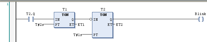
IEC 61131-3 defines a complete LD command set, consisting of different types of contacts and coils. Contacts conduct the current (according to their type) from left to right. Coils store the incoming value. Contacts and coils are assigned to Boolean variables. You can supplement an LD network by jumps, returns, labels and comments.