


|
This is the web edition of the original ⮫ AC500-S safety user manual, version 1.3.2. This web edition is provided for quick reference only. The original safety user manual must be used to meet functional safety application requirements. |
|
Digital inputs |
16 (24 V DC) |
|
LED displays |
for signal status, module errors, channel errors and supply voltage |
|
Internal power supply |
through the I/O bus interface |
|
External power supply |
via the terminals ZP and UP (process voltage 24 V DC) |
Self-tests and diagnostic functions (both start-up and runtime), like CPU and RAM tests, program flow control, cross-talk and stuck-at-1 tests, etc. are implemented in DI581-S according to IEC 61508 SIL 3 requirements.

NOTICE
Only F_Dest_Add is used for PROFIsafe F-Device identification in DI581-S.
DI581-S contains 16 safety digital input channels with the following features:
-
Phase-shifted (unique) test pulses T0 ... T7 can be used for connection of mechanical sensors. Test pulse outputs T0 ... T7 provide 24 V signal with a short phase-shifted unique pulses (0 V) of 1 ms. Since the test pulses on each of the test pulse output channels are unique (due to the phase shift), they can be used to monitor the cross-talk between the given input channel with connected test pulse output and another wire, e.g, with 24 V DC, another test pulse output, etc. Test pulse outputs are dedicated ones:
-
T0 can be used only with input channels I0 and I1
-
T1 can be used only with input channels I2 and I3
-
T2 can be used only with input channels I4 and I5
-
T3 can be used only with input channels I6 and I7
-
T4 can be used only with input channels I8 and I9
-
T5 can be used only with input channels I10 and I11
-
T6 can be used only with input channels I12 and I13
-
T7 can be used only with input channels I14 and I15
-
-
Input delay with the following values: 1 ms, 2 ms, 5 ms, 10 ms, 15 ms, 30 ms, 50 ms, 100 ms, 200 ms, 500 ms. Input delay value of 1 ms is the minimum one.
NOTICE
The allowed signal frequency on safety digital inputs is dependent on the input delay value for the given channel:
-
For channel input delay values of 1 ... 10 ms, the pulse length of input signal shall be ³ 15 ms (~ 65 Hz) to avoid occasional input channel passivation.
-
For channel input delay of 15 ms, the pulse length of input signal shall be ³ 20 ms (~ 50 Hz) to avoid occasional input channel passivation.
-
For channel input delay of 30 ms, the pulse length of input signal shall be ³ 40 ms (~ 25 Hz) to avoid occasional input channel passivation.
-
For channel input delay of 50 ms, the pulse length of input signal shall be ³ 60 ms (~ 15 Hz) to avoid occasional input channel passivation.
-
For channel input delay of 100 ms, the pulse length of input signal shall be ³ 120 ms (~ 8 Hz) to avoid occasional input channel passivation.
-
For channel input delay of 200 ms, the pulse length of input signal shall be ³ 250 ms (~ 4 Hz) to avoid occasional input channel passivation.
-
For channel input delay of 500 ms, the pulse length of input signal shall be ³ 600 ms (~ 1.5 Hz) to avoid occasional input channel passivation.

DANGER
The input delay parameter means that signals with the duration shorter than input delay value are always not captured by the safety module.
The signals with the duration of equal to or longer than "input delay parameter" + "input delay accuracy" are always captured by the safety module, provided that the allowed frequency (refer to previous notice) of the safety input signal is not exceeded.
The "input delay accuracy" can be estimated based on the following assumptions:
-
If no test pulses are configured for the given safety digital input, then input delay accuracy can be calculated as 1 % of set input delay value (however, input delay accuracy value must be at least 0.5 ms!).
-
If test pulses are configured for the given safety digital input of DI581-S module, then the input delay accuracy values can be estimated based on the input delay parameter value⮫ Table 980 “Input delay accuracy for DI581-S”.
|
Input delay (ms) |
Input delay accuracy (ms) |
|---|---|
|
1 |
2 |
|
2 |
2 |
|
5 |
3 |
|
10 |
4 |
|
15 |
5 |
|
30 |
6 |
|
50 |
7 |
|
100 |
10 |
|
200 |
15 |
|
500 |
25 |
-
Checking of process power supply (diagnostic message is sent from the safety I/O module to the CPU informing about the lack of process power supply for the given safety I/O module). This function is a non-safety one and is not related to the internal safety-relevant over- and undervoltage detection.
-
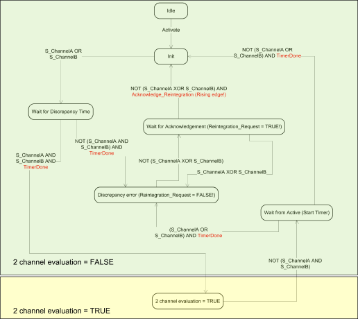
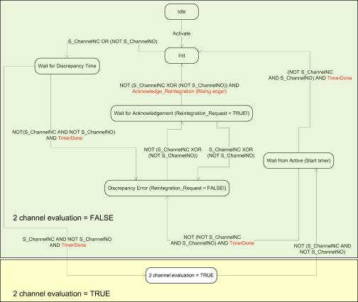
2 channel equivalent and 2 channel antivalent mode with discrepancy time monitoring (configurable 10 ms ... 30 s).
NOTICE
In a 2 channel mode, the lower channel (channels 0/8 ➔ Channel 0, channels 1/9 ➔ Channel 1, etc.) transports the aggregated process value, PROFIsafe diagnostic bit, acknowledgment request and acknowledge reintegration information. The higher channel always provides the passivated value "0".
DANGER
After discrepancy time error, the relevant channels are passivated. As soon as a valid sensor state is observed (equivalent or antivalent, depending on the selected mode), reintegration request status bit for the given channel becomes TRUE. You can acknowledge an error using acknowledge reintegration command bit for the given channel. This can directly lead to the machine start, because both TRUE - TRUE and FALSE - FALSE are valid states for equivalence and both TRUE - FALSE and FALSE - TRUE are valid states for antivalence.
Make sure that such behavior is acceptable in your safety application. If no, then you can use either included PLCopen Safety POUs for 2 channel evaluation in your safety program or write your own POUs for 2 channel evaluation on the safety CPU.
NOTICE
2 channel equivalent and 2 channel antivalent modes are implemented in DI581-S and DX581-S module to handle relatively static safety signals, e.g., those for emergency stop devices.
If frequently changing signals, like those from light curtains, laser scanners, door switches, etc. must be handled by DI581-S and DX581-S, then it is highly recommended to use input delay of 1 ms for these channels or to configure related channels in 1 channel mode and do 2 channel equivalent and 2 channel antivalent evaluation at the safety CPU using PLCopen Safety FBs SF_Equivalent⮫ “SF_Equivalent” and SF_Antivalent⮫ “SF_Antivalent”.