

|
This is the web edition of the original ⮫ AC500-S safety user manual, version 1.3.2. This web edition is provided for quick reference only. The original safety user manual must be used to meet functional safety application requirements. |
Elements of the module
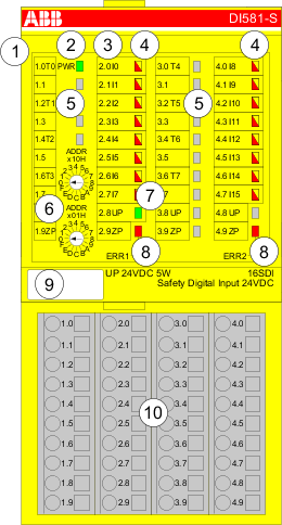
1
I/O bus
2
System LED
3
Allocation terminal no. - signal name
4
16 yellow/red LEDs signal status I0 ... I7/I8 ... I15
5
8 unique phase-shifted test pulse outputs T0 ... T3/T4 ... T7
6
2 rotary switches for PROFIsafe address
7
Green LED for process voltage UP
8
Red LEDs to display module errors
9
Label (TA525)
10
I/O terminal unit (TU582-S)
-
Purpose
-
Functionality
-
Mounting, dimensions and electrical connection
-
Internal data exchange
-
I/O configuration
-
Parameterization
-
Circuit examples DI581-S
-
LED status display
-
Technical data
-
Ordering data