


|
This is the web edition of the original ⮫ AC500-S safety user manual, version 1.3.2. This web edition is provided for quick reference only. The original safety user manual must be used to meet functional safety application requirements. |
Write your safety application program and pay attention to system start-up procedure.

NOTICE
⮫ How to create, configure, modify and download a valid boot project for non-safety CPUs.
To avoid unexpected configuration errors, as a first step, download a valid project to non-safety CPU. As a second step, download a safety project to the safety CPU.
-
Program and download a valid project to non-safety CPU.
-
Start AC500-S Programming Tool by double-clicking safety application node, e.g., “AC500_S”.
Before AC500-S Programming Tool is started, you may be asked to update your configuration. It is needed to transfer the updated configuration data (e.g., variable names, etc.) to AC500-S Programming Tool.
Fig. 470: AC500-S Programming Tool 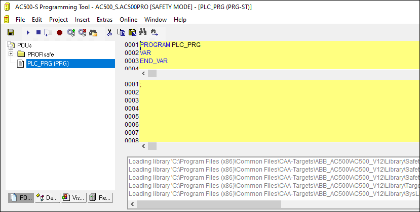

DANGER
Make sure that when AC500-S Programming Tool is started, the following properties can be observed:
-
Yellow background
-
SAFETY MODE is visible in the title bar
NOTICE
When AC500-S Programming Tool is started for the first time in the Automation Builder project, you will be asked to manually confirm included safety library identification data (version number and CRC). After this, safety library identification data are saved in the project.
If you change the safety library content and replace it on your hard disk, the next time you start AC500-S Programming Tool you will be informed that one of the safety libraries changed. In the properties window for safety libraries you will still observe an initially saved CRC value. However, when you compile the project, you will get a CRC error message. The project will not be compiled by AC500-S Programming Tool because of the changed library.
To compile the project successfully, manually delete the selected safety library and add a new safety library with a new CRC. The new safety library with new CRC will be accepted and no compilation error will be shown.
-
-
Define your user management for AC500-S Programming Tool.
All user management features of AC500-S Programming Tool are available for project administrator.
⮫ “User and access rights management”
The project administrator has to set a user password for newly created safety project. Go to “Project User Group Passwords...” and set the password for Level 0 User Group, which shall represent users from safety user group in Automation Builder.
Fig. 471: Set passwords 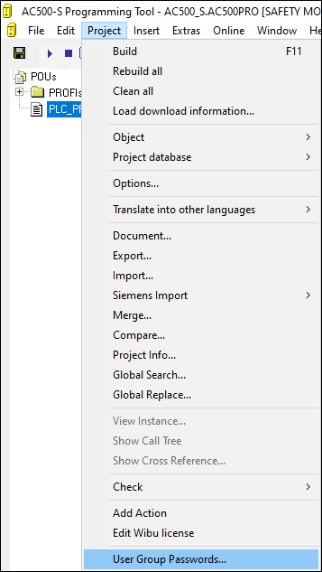
-
Check your F-Device configuration in AC500-S Programming Tool.
If your configuration of F-Devices is final, you have to check that F-Parameter values from F-Parameter tab are the same as those imported to AC500-S Programming Tool: Go to “Resources” tab in the safety project. Navigate to “Global Variables PROFIsafe” and select the F-Device instance you want to check.
DANGER
You have to formally confirm that F-Parameter values from F-Parameter tab are the same as those imported to AC500-S Programming Tool (item 3 in⮫ “Checklist for creation of safety application program”).
Fig. 472: F-Parameter values in AC500-S Programming Tool 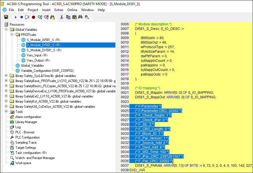
-
All configured input and output variables can be found in separate global variable lists.
Fig. 473: Global variable list in AC500-S Programming Tool 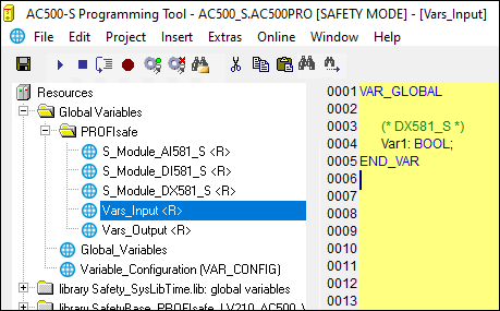
DANGER
It is not allowed to change read-only (see <R> sign) resources, task configuration and pre-certified POUs (CallbackInit, CallbackReadInputs, CallbackWriteOutputs, InitPROFIsafe, ReadPROFIsafeInputs, WritePROFIsafeOutputs) under PROFIsafe folder in AC500-S Programming Tool. A change of <R> resources could lead to inconsistencies between Automation Builder and safety project.
NOTICE
All configured safety input and output variables can also be seen in non-safety project (e.g., for their visualization in operator panels, data logging, etc.).
The difference comparing to safety project is that end-user is not able to modify the values of those safety variables from non-safety project. It is prohibited by proper design.
-
Check the validity of the safety libraries.
In Library Manager, check that the CRCs of the used safety libraries are as listed in⮫ Table 990 “Safety libraries”.
Fig. 474: All available safety libraries can be found in the Library Manager 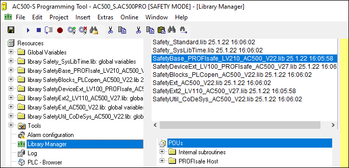
DANGER
The user is responsible to check that only certified safety libraries are used in his project. Refer to the overview of certified safety libraries and CRCs⮫ “Overview”.
The user alone is responsible for all libraries which are created by him and referenced in the project for use in safety applications.
You have to formally confirm that no non-safety libraries are used in your safety application (item 19 in⮫ “Checklist for creation of safety application program”).
NOTICE
AC500-S safety CPU is a single-task machine, thus, no task configuration is needed.
-
Start programming your safety application.
The safety application program must be identified using the following properties: project name, file name, change date, title, author, version, description and CRC. Using menu item “Online Check boot project in PLC”, one can check that offline safety project and the boot project on the safety CPU are identical.
Forcing of variables is supported by the safety CPU, but only in DEBUG (non-safety) mode, which means that user takes over a complete responsibility for potential damages due to wrong system behavior in the DEBUG (non-safety) mode.
DANGER
Forcing of variables in the safety CPU is only allowed after consulting the approving board responsible for site approval in operational customer applications. During forcing, the user in charge must ensure sufficient safety technical monitoring of the process by other technical, organizational and structural measures.
For safety applications developed with AC500-S, visualizations in AC500-S Programming Tool are allowed for debugging and maintenance purposes only.
DANGER
Changing values via controls (e.g., "Write values") would cause the safety CPU to switch to a DEBUG RUN mode, which is non-safe.
In case of an activation of DEBUG RUN (non-safety) mode on the safety CPU, the responsibility for safe process operation lies entirely with the organization and person responsible for the activation of DEBUG RUN (non-safety) mode.
NOTICE
ST, FBD and LAD are the only IEC 61131 languages supported by the safety CPU for safety programming. Pay attention to the safety programming guidelines⮫ “Safety programming guidelines”. ST with a subset defined in ⮫ Chapter is equivalent to the limited variability language, as defined in IEC 61508.
NOTICE
Do not create global variable lists using names beginning with the prefix "S_Module_". Global variable lists starting with "S_Module_" will be automatically updated by the AC500-S Programming Tool and may lead to the loss of the user information.
For the safety PLC, it is important that all F-Devices are successfully initialized before program logic execution starts. F-Devices start in FV_activated mode⮫ more details on PROFIsafe F-Host stack: Chapter“SafetyBase_PROFIsafe_LV210_AC500_V22.lib”. To realize a simultaneous start, we recommend using an own special POU, similar to SF_Startup explained below, which handles various possible start-up scenarios in PROFIsafe specification⮫ [2] and then gives "Ready" output as a trigger for further normal safety program logic execution. As you can see from the implementation below, it is enough if at least one of the channels in DI581-S module has PROFIsafe diagnostic bit set to 1, meaning that normal process values can be delivered.
Declaration part
FUNCTION_BLOCK SF_StartupVAR_OUTPUTReady: BOOL; (* Set to TRUE if all safety modules are initialized *)END_VARVAR bTempReady: BOOL; (* Set to TRUE if DI581-S safety module is ready *)END_VARVAR CONSTANT_TRUE: BOOL := TRUE; (* Constant because TRUE is a literal *) _FALSE: BOOL := FALSE; (* Constant because FALSE is a literal *) wdNull: WORD := 16#0000; (* Constant for Safety I/O initialization *)END_VARVAR_EXTERNAL DI581_S: PROFIsafeStack; (* External declaration *)END_VARImplementation part
(* Check if operator acknowledge is required for F-Device *)IF DI581_S.OA_Req_S THEN (* The module requests an acknowledgment? *)DI581_S.OA_C := DI581_S.OA_Req_S; (* Acknowledge it, if requested *)(* IS_DI581_Started is the input variable for all channel PROFIsafe diagnostic bits set in Control Builder Plus / Automation Builder for DI581-S module *)ELSIF IS_DI581_Started > wdNull THEN (* Is this module initialized? *)bTempReady := _TRUE; (* Yes, the module is initialized *)ELSEbTempReady := _FALSE; (* No, the module is not initialized yet *)END_IF;IF bTempReady THEN (* Set POU output signal *)Ready := _TRUE;ELSE Ready := _FALSE;END_IF;NOTICE
To acknowledge the F-Device after a module passivation, OA_C command bit has to be toggled from ‘0’ to ‘1’ until OA_Req_S status bit becomes "0".
-
Set up correct communication parameters.
Fig. 475: Set communication parameters 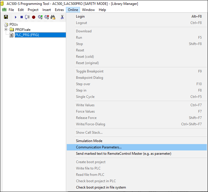
NOTICE
Make sure that to download safety project, either “ABB Tcp/Ip Level 2 AC” or “ABB RS232 AC” communication channels were selected.
Fig. 476: Example with Ethernet connection 
Note that "Address" is the IP address of your non-safety CPU, if supported on the non-safety CPU (you can also use COM port for program download using serial connection). Coupler (level 1) defines the position of the safety CPU (line 1 - position 1, line 2 - position 2 and so on).
⮫ “Setting up of communication parameters in Windows”
Fig. 477: Example with a serial connection 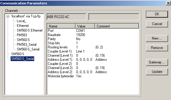
-
Download your safety application to the safety CPU.
You can transfer your safety program to the safety CPU from a PC or using an SD card.
⮫ “Download your safety program to the safety CPU from a PC”
⮫ “Download your safety program to the safety CPU from an SD card”
-
Download your safety program to the safety CPU from a PC
Download your safety application and create a boot project so that your safety CPU can start safety program execution after a power cycle.
NOTICE
The “Online Change” service is not supported by the safety CPU for safety reasons. It means that each program change of safety project requires stopping the safety CPU, downloading a new boot project and then executing a power cycle or rebooting through non-safety CPU to see the safety program change(s) become active.
NOTICE
Only one user can be logged-on to the given safety CPU at a time. It is needed to avoid multiple changes on the safety CPU from different users working at the same time.
The limitation on the number of open connections only exists for the safety CPU, which means that it is still possible to simultaneously connect to non-safety CPU, e.g., using web and OPC server functionality.
Fig. 478: Create boot project for the safety CPU 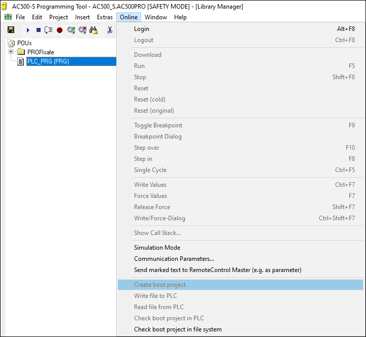
DANGER
If “Update Device...” function was used on safety modules, then a full functional testing of all parts of the safety application has to be performed. This test must be carried out with the machine in its final configuration including mechanical, electrical and electronic components, sensors, actuators and software.
NOTICE
Use menu item “Online Check boot project in PLC” to verify that offline project and the boot project on the safety CPU are identical (file name, change date, title, author, version, description and CRC).
The same comparison can be done with another boot project saved on the PC or SD card using “Online Check boot project in file system” menu item.
Note that before the boot project is created offline on the PC for a backup and later usage, the boot project has to be loaded at least once to the safety CPU.
It is highly recommended to execute “Clean All”, “Rebuild All” commands from “Project” menu before downloading the safety program to safety CPU.
NOTICE
The boot project CRC uniquely identifies the safety CPU boot project. Note that not only code changes but also different actions in the programming environment can lead to new boot project CRC.
User actions which change the safety boot project CRC:
-
In AC500-S Programming Tool:
-
Select tab “Resources”, open “Target settings” and press [OK] without any changes in the dialog.
-
Select “Project Options” and press [OK] without any changes in the dialog.
-
Select tab “Resources”, open “Workspace” and press [OK] without any changes in the dialog.
-
-
In Automation Builder:
-
Double-click on the safety CPU, go to the tab “CPU Parameters” and change any of the parameters, e.g., “Enable debug”. After that, open AC500-S Programming Tool (double-click on safety application node).
-
With AC500 V2 non-safety CPU: Double-click on the safety CPU, make changes in tab “Data exchange configuration” and open AC500-S Programming Tool (double-click on safety application node).
-
NOTICE
Remember that non-safety CPU takes part in iParameter transfer to F-Devices, thus, you shall not only download your safety application program to safety CPU, but also in a similar way download non-safety program to non-safety CPU and create a boot project for non-safety CPU.
⮫ “Updating an Application on the PLC ”
If you do not follow the recommendation above, you may face configuration error or passivation of some F-Devices.
DANGER
Do not use “Write file to PLC” command for the safety CPU because it may lead to the loss of important user information or load of corrupted data on the safety CPU.
Skip the next step and continue with the step after it.
-
-
Download your safety program to the safety CPU from an SD card
DANGER
If you transfer your safety program to safety CPU using SD card, you have to make sure that the inserted SD card contains the correct safety program. You can check this through program identification (e.g., boot project CRC) or other measures, such as a unique identifier on the SD card.
NOTICE
The safety CPU boot project can be updated via SD card only if no boot project is present on the safety CPU⮫ “Boot project update”.
-
Transfer the safety program to the SD card⮫ “Boot project update”.
-
Perform a program identification - check if SD card and offline (e.g., on PC) safety program CRCs match using “Online Check boot project in file system”.
-
Attach an appropriate label to the SD card.
The outlined procedure must be ensured through organizational measures.
-
-
You can use PLC browser commands after login on safety CPU.
The following PLC browser commands from AC500-S Programming Tool are supported by the safety CPU:
- ?
-
List of available browser commands
- reflect
-
Output of browser commands (for test purposes)
- pid
-
It shows the project ID
- pinf
-
It shows project information in AC500 format
- getprgprop
-
It shows program properties in AC500 format
- getprgstat
-
It shows program status in AC500 format
- setpwd
-
It sets safety CPU password (it is needed during login). This command is active only if safety CPU "Enable debug" parameter was set to "ON" and proper boot project was loaded to non-safety CPU.
- delpwd
-
It deletes safety CPU password. This command is active only if safety CPU "Enable debug" parameter was set to "ON" and proper boot project was loaded to non-safety CPU.
- rtsinfo
-
It shows firmware and boot project information in AC500 format
- proddata
-
It shows safety CPU production data in AC500 format
- diagreset
-
It resets diagnosis system of the safety CPU
- diagack all
-
It acknowledges all errors
- diagack x
-
It acknowledges all errors of class x (x= 1 .. 4)
- diagshow all
-
It shows all errors in AC500 format
- diagshow x
-
It shows all errors of class x
- delappl
-
It deletes boot project in the flash memory. This command is executed only in DEBUG STOP state of the safety CPU. After safety CPU restart, one shall check that no boot project is available in the safety CPU. This command is active only if safety CPU "Enable debug" parameter was set to "ON" and proper boot project was loaded to non-safety CPU.
- deluserdat:
-
It deletes user data in the flash memory. This command is executed only in DEBUG STOP state of the safety CPU. It is executed immediately and is active only if safety CPU "Enable debug" parameter was set to "ON" and proper boot project was loaded to non-safety CPU.
- applinfo
-
It shows the application information, e.g., results of time profiling using functions SF_APPL_MEASURE_BEGIN and SF_APPL_MEASURE_END.
- applinfo reset
-
It resets all application information, e.g., time measurement values.
- flashstatus
-
It shows the flash programming progress in the safety CPU in % when downloading boot code, firmware or a bootproject.
None of the above-mentioned safety CPU PLC browser commands changes the state (e.g., from RUN to DEBUG RUN or DEBUG STOP, etc.) of the safety CPU.
NOTICE
The following PLC browser commands from safety CPU can influence its state:
resetprg:
It prepares safety CPU restart with initial variable values. Safety CPU changes its state, e.g., from RUN to DEBUG STOP. This command is only accepted if safety CPU “Enable debug” parameter was set to “ON” and proper boot project was loaded to non-safety CPU.
resetprgorg:
It restores safety CPU original state (all variables, flash memory sections, etc. get original values). Safety CPU changes its state, e.g., from RUN to DEBUG STOP. This command is only accepted if safety CPU “Enable debug” parameter was set to “ON” and proper boot project was loaded to non-safety CPU.
DANGER
The results of “delappl”, “resetprgorg”, “setpwd” and “delpwd” command execution shall be checked by the end-user through a log-on after a power cycle of the safety CPU.
-
Safe CPU to CPU communication using SM560-S-FD-1 and SM560-S-FD-4