


This tab is displayed in device editors for devices with I/O channels. It shows the available channels and allows for the mapping of input, output, and memory addresses of the controller to variables or entire function blocks of the application. You create the 'I/O Mapping' in this way.
For more information, see: ⮫ “Configuring Devices and I/O Mapping ”, ⮫ “Linking a device input with an existing project variable ("mapping") ”, ⮫ “Mapping a device input to a recently created project variable ”, ⮫ “Linking a device with a function block instance ”, ⮫ “Changing and fixing an address value in the I/O map ”, ⮫ “Configuration of the I/O variable update ”, ⮫ “Monitoring of variables in the I/O map in online mode ”, ⮫ “Generating implicit variables for the forcing of I/Os ”, ⮫ “I/O mapping in one dialog for multiple devices ”
The application that is to take care of the I/O handling is defined on the “PLC Settings” tab.
You can use the "Online Configuration Mode" if the device supports it. In this mode, you can access the I/Os of the hardware without having to download an actual application to the device beforehand.
If an I/O channel is not referenced in the application, then its value will not be updated. If you want to monitor non-referenced I/O channels, then you need to enable the “Always update variables” option on the ⮫ “Tab: PLC Settings ”. Alternatively, you could also enable this option on the “I/O Mapping” tab of a device. Then enabling is valid only for this one device and its children.

NOTICE
Mapping data types which are "too large"
If a variable of a data type that is larger than a byte is mapped to a byte address, the value of the variable will be truncated to byte size there. For monitoring the variable value in the “I/O Mapping” dialog, this means that, in the root element of the address, the value is displayed which the variable currently has in the project. The current individual bit values of the byte are displayed in succession in the bit elements below that, but this may not be sufficient for the entire variable value.
Example of the “<device name> I/O Mapping” tab for a CAN bus slave:
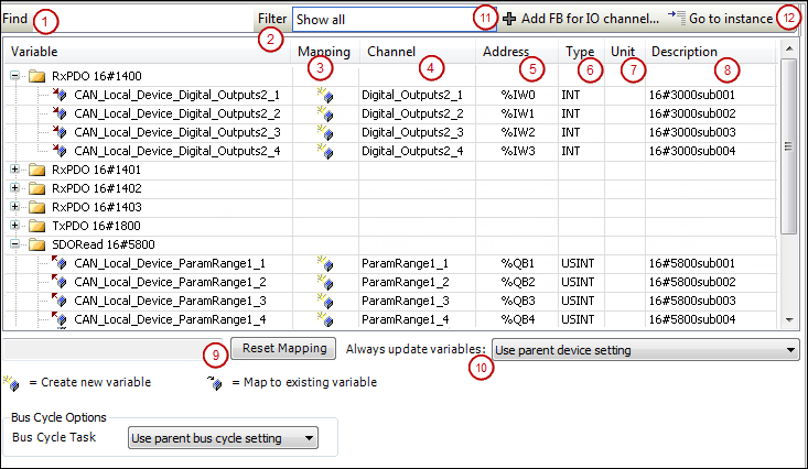
The tab contains a table for editing the I/O mapping. The information displayed for the inputs and outputs originates from the device description.
|
“Find” (1) |
Input field for a string to search for in the mapping table The search results are highlighted in yellow. |
|
“Filter” (2) |
List box with filters for the I/O mappings displayed in the mapping table:
|
|
|
Depending on the device, available if the channel entry is selected in the mapping table Opens the “Select Function Block” dialog for selecting the function block that should be linked directly to the channel |
|
|
Available if the entry is selected in the mapping table Jumps to the corresponding entry on the “<device name> IEC Objects” tab |
|
“Variable” |
Depending on the device, the inputs and outputs of the device are displayed as nodes and below them, indented, the associated channels or, depending on the device, only the implicitly created device instance. The symbol indicates the type of channel:
Double-click the cell to open an input field.
Depending on the device, inputs or outputs can be linked directly to a function block.
In this case, the |
|
“Mapping” (3) |
Type of mapping:
|
|
“Channel” (4) |
Symbolic name of the channel. |
|
“Address” (5) |
Address of the channel (example: Address strikethrough: Indicates that you should not assign any more variables to this address. Reason: Although the variable specified here is managed – as an existing variable –at a different memory location, ambiguity could result when the values are written, particularly with outputs.
If the arrangement of the device objects in the device tree changes, then CODESYS does not adapt this address automatically. |
|
“Type” (6) |
Data type of the channel (example: Structures or bit fields defined in the device description are displayed only if they are part of the IEC standard and are identified as IEC data types in the device description. Otherwise the table cell remains empty. When mapping structured variables, the editor prevents you from specifying both the
structure variable (example: |
|
“Default Value” |
Default value of the parameter that applies to the channel: Appears only if the option “Set all outputs to default” is selected in the “PLC Settings” for the behavior of the outputs at stop. Note: For compiler version V3.5 SP11 and higher, the initialization value of the variables is used automatically as the default value when mapping to an existing variable. You can edit the “Default value” field only if you map to a new created variable or if no mapping is specified. In older versions, users had to specify explicitly that the default value and initialization value were identical. |
|
“Unit” (7) |
Unit for the parameter value (example: |
|
“Description” (8) |
Short description of the parameter |
|
“Current value” |
Actual value of the parameter applied to the channel; displayed in online mode only |


 : Input
 : Output

 : Existing variable
 : New variable
 : Mapping to function block instance
 : Indicates that this address has been edited and fixed
The change of the default value by an online change is allowed, however the value is applied only after a "Reset cold" or "Reset warm".
|
“Reset Mapping” (9) |
CODESYS resets the mapping settings to the default values as defined in the device description file. |
|
“Always update variables” (10) |
Definition for the device object about updating I/O variables The default value is defined in the device description:
|
If a UNION is represented by I/O channels in the mapping dialog, it depends on the device whether mapping to the root element is also possible.
For more information, see: ⮫ “Fieldbus Devices and I/O Drivers ”
-
See also: ⮫ <device name> IEC Objects