


|
Parameter |
Value |
||
|---|---|---|---|
|
Number of channels per module |
4 |
||
|
Distribution of the channels into groups |
1 group of 4 channels |
||
|
Galvanic isolation |
Yes, per group |
||
|
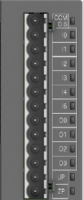
Connection of the channels O0 to O3 |
Terminals 8 to 11 |
||
|
Common power supply voltage |
Terminals 12 (+24 V DC, signal name UP) |
||
|
Reference potential for the channels O0 to O3 |
Terminal 13 (0 V DC, negative pole of the process voltage, signal name ZP) |
||
|
Indication of the output signals |
1 yellow LED per channel; the LED is on when the output signal is high (signal 1) |
||
|
Way of operation |
Non-latching type |
||
|
Min. output voltage at signal 1 |
UP - 0.1 V |
||
|
Output delay (max. at rated load) |
|||
|
0 to 1 |
On request |
||
|
1 to 0 |
On request |
||
|
Rated protection fuse (per channel) |
2 A fast |
||
|
Output current |
|||
|
Rated current per channel (max.) |
0.5 A at UP 24 V DC (resistance, general use and pilot duty) |
||
|
Rated current per group (max.) |
2 A |
||
|
Rated current (all channels together, max.) |
2 A |
||
|
Max. leakage current with signal 0 |
On request |
||
|
Demagnetization when inductive loads are switched off |
Must be performed externally according to driven load specification |
||
|
Switching Frequencies |
|||
|
With inductive loads |
On request |
||
|
Short-circuit-proof / Overload-proof |
No |
||
|
Overload message |
No |
||
|
Output current limitation |
No |
||
|
Resistance to feedback against 24 V DC |
No |
||
|
Connection of 2 outputs in parallel |
Not possible |
||
|
Max. cable length *) |
|||
|
Shielded |
500 m |
||
|
Unshielded |
150 m |
||
*) For PWM and PTO outputs, a shielded cable must be used.
|
Parameter |
Value |
||
|---|---|---|---|
|
Number of channels per module |
8 |
||
|
Distribution of the channels into groups |
1 group of 8 channels |
||
|
Galvanic isolation |
Yes, per group |
||
|
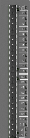
Connection of the channels O0 to O7 |
Terminals 14 to 21 |
||
|
Common power supply voltage |
Terminals 24 (+24 V DC, signal name UP) |
||
|
Reference potential for the channels O0 to O7 |
Terminal 25 (0 V DC, negative pole of the process voltage, signal name ZP) |
||
|
Indication of the output signals |
1 yellow LED per channel; the LED is on when the output signal is high (signal 1) |
||
|
Way of operation |
Non-latching type |
||
|
Min. output voltage at signal 1 |
UP - 0.1 V |
||
|
Output delay (max. at rated load) |
|||
|
0 to 1 |
On request |
||
|
1 to 0 |
On request |
||
|
Rated protection fuse (per channel) |
2 A fast |
||
|
Output current |
|||
|
Rated current per channel (max.) |
0.5 A at UP 24 V DC (resistance, general use and pilot duty) |
||
|
Rated current per group (max.) |
4 A |
||
|
Rated current (all channels together, max.) |
4 A |
||
|
Max. leakage current with signal 0 |
0.5 mA |
||
|
Demagnetization when inductive loads are switched off |
Must be performed externally according to driven load specification |
||
|
Switching Frequencies |
|||
|
With inductive loads |
On request |
||
|
Short-circuit-proof / Overload-proof |
No |
||
|
Overload message |
No |
||
|
Output current limitation |
No |
||
|
Resistance to feedback against 24 V DC |
No |
||
|
Connection of 2 outputs in parallel |
Not possible |
||
|
Max. cable length *) |
|||
|
Shielded |
500 m |
||
|
Unshielded |
150 m |
||
*) For PWM and PTO outputs, a shielded cable must be used.