


|
Parameter |
Value |
||
|---|---|---|---|
|
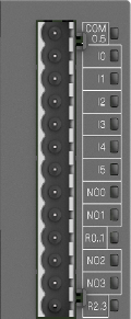
Number of channels per module |
4 normally-open relay outputs |
||
|
Distribution of the channels into groups |
2 groups for 2 channels |
||
|
Galvanic isolation |
Yes, per group |
||
|
Connection of the channels NO0 to NO1 |
Terminals 8 to 9 |
||
|
Connection of the channels NO2 to NO3 |
Terminals 11 to 12 |
||
|
Reference potential R0..1 for the channels NO0 to NO1 |
Terminal 10 |
||
|
Reference potential R2..3 for the channels NO2 to NO3 |
Terminal 13 |
||
|
Relay output voltage |
|||
|
Rated value |
24 V DC or 100 V AC ... 240 V AC 50 Hz/60 Hz |
||
|
Range |
5 V DC ... 30 V DC or 5 V AC ... 250 V AC |
||
|
Indication of the output signals |
1 yellow LED per channel; the LED is on when the output signal is high (signal 1) |
||
|
Way of operation |
Non-latching type |
||
|
Output delay |
|||
|
0 to 1 |
Typ. 10 ms |
||
|
1 to 0 |
Typ. 10 ms |
||
|
Output current |
|||
|
Rated current per channel (max.) |
2.0 A (24 V DC resistance and general use, 100 V AC ... 240 V AC, resistance, general use and pilot duty) |
||
|
Rated current per group (max.) |
6 A |
||
|
Rated current (all channels together, max.) |
12 A |
||
|
Demagnetization when inductive loads are switched off |
External demagnetization measures must be implemented when switching inductive loads. |
||
|
Spark suppression with inductive AC loads |
Must be performed externally according to driven load specification |
||
|
Switching frequencies |
|||
|
With resistive loads |
Max. 1 Hz |
||
|
With inductive loads |
On request |
||
|
With lamp loads |
On request |
||
|
Short-circuit-proof / Overload-proof |
No, should be provided by an external fuse or circuit breaker |
||
|
Rated protection fuse (for each channel) |
5 A fast |
||
|
Overload message |
No |
||
|
Output current limitation |
No |
||
|
Resistance to feedback against 24 V DC |
No |
||
|
Connection of 2 outputs in parallel |
Not possible |
||
|
Lifetime of relay contacts (cycles) |
100,000 at rated load |
||
|
Max. cable length *) |
|||
|
Shielded |
500 m |
||
|
Unshielded |
150 m |
||
*) For PWM and PTO outputs, a shielded cable must be used.
|
Parameter |
Value |
||
|---|---|---|---|
|
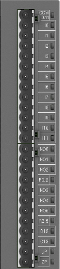
Number of channels per module |
6 normally-open relay outputs |
||
|
Distribution of the channels into groups |
2 groups for 3 channels |
||
|
Galvanic isolation |
Yes, per group |
||
|
Connection of the channels NO0 to NO2 |
Terminals 14 to 16 |
||
|
Connection of the channels NO3 to NO5 |
Terminals 18 to 20 |
||
|
Reference potential R0..2 for the channels NO0 to NO2 |
Terminal 17 |
||
|
Reference potential R3..5 for the channels NO3 to NO5 |
Terminal 21 |
||
|
Relay output voltage |
|||
|
Rated value |
24 V DC or 100 V AC ... 240 V AC 50 Hz/60 Hz |
||
|
Range |
5 V DC ... 30 V DC or 5 V AC ... 250 V AC |
||
|
Indication of the output signals |
1 yellow LED per channel; the LED is on when the output signal is high (signal 1) and the module is powered through the I/O bus |
||
|
Way of operation |
Non-latching type |
||
|
Output delay |
|||
|
0 to 1 |
Typ. 10 ms |
||
|
1 to 0 |
Typ. 10 ms |
||
|
Output current |
|||
|
Rated current per channel (max.) |
2.0 A (24 V DC resistance and general use, 100 V AC ... 240 V AC, resistance, general use and pilot duty) |
||
|
Rated current per group (max.) |
6 A |
||
|
Rated current (all channels together, max.) |
12 A |
||
|
Demagnetization when inductive loads are switched off |
External demagnetization measures must be implemented when switching inductive loads. |
||
|
Spark suppression with inductive AC loads |
Must be performed externally according to driven load specification |
||
|
Switching frequencies |
|||
|
With resistive loads |
Max. 1 Hz |
||
|
With inductive loads |
On request |
||
|
With lamp loads |
On request |
||
|
Short-circuit-proof / Overload-proof |
No, should be provided by an external fuse or circuit breaker |
||
|
Rated protection fuse (for each channel) |
5 A fast |
||
|
Overload message |
No |
||
|
Output current limitation |
No |
||
|
Resistance to feedback against 24 V DC |
No |
||
|
Connection of 2 outputs in parallel |
Not possible |
||
|
Lifetime of relay contacts (cycles) |
100,000 at rated load |
||
|
Max. cable length *) |
|||
|
Shielded |
500 m |
||
|
Unshielded |
150 m |
||
*) For PWM and PTO outputs, a shielded cable must be used.