CtrlPiPulse (FB)
FUNCTION_BLOCK CtrlPiPulse EXTENDS AbbLConC3
This function block reacts as a PI step controller with digital pulse outputs to control two digital actuators. This is typically used in special HVAC applications with two different control properties e.g. heating and cooling.
Main features of the function block include-
Pulse output
Manual control mode
Input procesing
Feedback loop
Three step hysteresis relay
Pulse Generator
This Function Block performs as a PI step controller with digital pulse outputs to control 2 digital actuators.
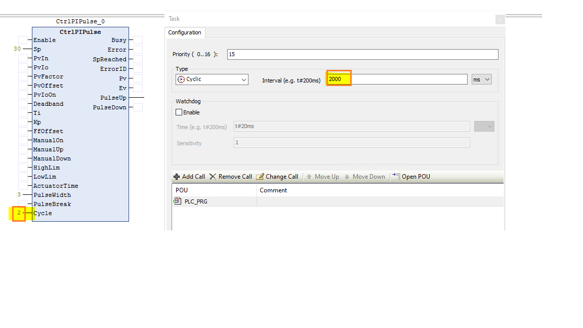
The PLC task time (Unit: milliseconds) needs to be same as the “Cycle” (Unit :Seconds)input of the function block.
Note
The ActuatorTime needs to be > = 30 * Cycle, if not the ActuatorTime will be set to = 30 * Cycle internally
- InOut:
Scope
Name
Type
Initial
Comment
Input
SpREAL0.0
2: Set point input for PI step controller
PvInREAL0.0
3: Process variable input in floating point format
PvIoINT0
4: Process variable in IO format, PvIn=(PvIo*100/27648) * PvFactor + PvOffset
PvFactorREAL1
5: Process variable factor is used to adapt the process variable range
PvOffsetREAL0.0
6: Process variable offset is used to adapt the process variable range
PvIoOnBOOLFALSE
7: Turn on process variable input channel in IO format with PvIo
DeadbandREAL0.0
8: Dead band of Error variable, Deadband>=0
TiREAL10
9: Time response of the integrator (Unit: Second) 10000.0>= Ti >= 0.1
KpREAL1
10: Propotional gain input sets of PI controller
FfOffsetREAL0.0
11: Feed forward offset for Manipulated variable
ManualOnBOOLFALSE
12: Turn on manual mode for controlling PulseUp / PulseDown actuating signals: FALSE- Automatic mode, TRUE- Manual mode
ManualUpBOOLFALSE
13: When Manual mode is on, generate actuating signal for “PulseUp” output manually.This should not be in combination with ManualDown.
ManualDownBOOLFALSE
14: When Manual mode is on, generate actuating signal for “PulseDown” output manually.This should not be in combination with ManualUp.
HighLimBOOLFALSE
15: Connect to high limit of position feedback signal, HighLim = True means the actuator is at upper limit stop
LowLimBOOLFALSE
16: Connect to low limit of position feedback signal, LowLim = True means the actuator is at lower limit stop
ActuatorTimeREAL30
17: Motor actuating time is the time required by actuator to move from one limit stop to next limit stop.(Unit = Second), 10000 >= ActuatorTime > 0.1. Unit = Seconds.
PulseWidthREAL3
18: Minimum pulse width (Unit: Second) PulseWidth>=0.The PulseUp Output should have a logic “one” pulse width >= PulseWidth Input.
PulseBreakREAL6
19: Minimum pulse break (Unit: Second) PulseBreak>=0.The PulseDown Output should have a logic “zero” pulse width >= PulseBreak Input.
CycleREAL1
20: Cycle = PLC task cycle time (Unit: Second). Cycle>=0
Output
ErrorID2: Error Code.Error identifier if an invalid value was applied to an input
SpReachedBOOLFALSE
3: Controlling state of the PI step controller, SpReached=TRUE means process variable (PV) reaches set point (SP)
PvREAL0.0
4: Process variable output of PI step controller
EvREAL0.0
5: Error variable of the set point and the process variable
PulseUpBOOLFALSE
6: Pulse signal up, generates actuating signal to open actuating valve
PulseDownBOOLFALSE
7: Pulse signal down, generates actuating signal to open actuating valve