


Device handling
In the application programming environment, devices represent hardware. The device description file contains information about the target device (drive) from the programming point of view like the device identifier, compiler type and memory size. The Automation Builder installation package installs the device description files automatically.
The device description may be updated later and a new file can be installed. The system monitors that a project with an incompatible device description file is not loaded to the drive.
User Lock
With the User Lock feature you can enable and disable IEC Programming for ABB ACS880 drives directly from Automation Builder, without needing Drive Composer pro. This makes it easier and faster to unlock drives for programming.
It is useful in the following cases:
-
You try to log in to a drive, but IEC Programming is disabled.
-
You want to enable IEC Programming for one or multiple drives at once.
-
You want to avoid switching between Automation Builder and Drive Composer pro.
To enable the User Lock feature:
-
Open Automation Builder with the IEC Programming component installed.
-
Create an ACS880 project and open the “Drives” window.
-
Scan and log in to your connected drives.
If login fails with a message “Enable IEC Programming”, proceed to the next step.
-
Open the “Open Communication” dialog.
-
Scan for drives again — drives with the same passcode can be selected together.
-
Choose how to proceed:
-
Use “Default Passcode”, or
-
Enter a “Custom Passcode”
The tool automatically updates each selected drive:
-
Writes passcode to parameter 96.2 or 196.2
-
Enables IEC Programming (bit 9 of 96.102 or 196.102)
-
Closes the lock by writing a random value to 96.2.
-
-
When you are done, try to log in again — you now have full IEC access.
Supported Drives
User Lock is supported only for ABB ACS880 drives with the following firmware:
|
Drive types |
Device ID |
Introduced firmware |
Userlock bit |
|
ACS880 AINF_BCU |
1612 8002 |
3.47 |
96.102-bit 9 |
|
ACS880 AINF_ZCU |
1612 0010 |
3.47 |
96.102-bit 9 |
|
ACS880 AISF_ZCU |
1612 0050 |
3.43 |
196.102-bit 9 |
|
ACS880 AISF_BCU |
1612 8050 |
3.43 |
196.102-bit 9 |
|
ACS880 ATBF_ZCU |
1612 0053 |
3.44 |
96.102-bit 9 |
|
ACS880 ATBF_BCU |
1612 8053 |
3.44 |
96.102-bit 9 |
|
ACS880 APCF_ZCU |
1612 0016 |
1.04.0.5 |
96.102-bit 9 |
|
ACS880 APCF_BCU |
1612 8016 |
1.04.0.5 |
96.102-bit 9 |
|
ACS880 YINFB_UCU22 |
1612 0008 |
1.30 |
96.102-bit 9 |
|
ACS880 YISFB_UCU22 |
1612 0058 |
1.30 |
196.102-bit 9 |
|
ACS880 YDIFB_UCU22 |
1612 0059 |
1.30 |
196.102-bit 9 |
|
ACS880 YINFC_UCU20 |
1612 0007 |
1.30 |
96.102-bit 9 |
-
Based on the drive firmware, passcode needs to write to 96.2 or 196.2.
-
Firmware version also needs to be validated.
-
You can disable IEC programming using the [Lock] button
Viewing device information
In the Automation Builder device tree, double-click on “Device” and go to “Information” tab to view the general information of a device.
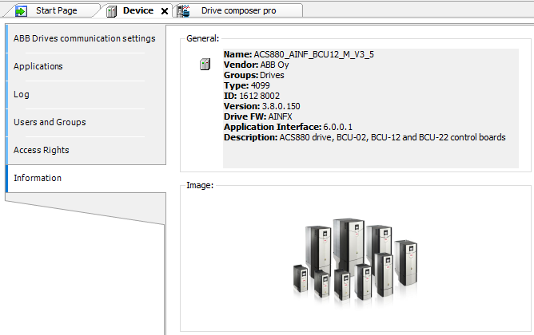
The device ID, drive FW name (AINFX) and application interface version must be identical in the project and drive target. In Drive Composer pro, use the system info option to check that the drive target has the corresponding application interface version, device type and drive firmware name (displayed in parameter 7.04).
You can also check if the drive target has the corresponding application interface version and device ID.
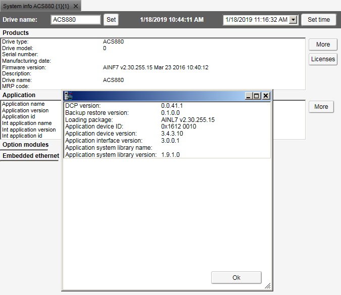
In Drive Composer pro, go to “System info Products More”.

The name and version of the available system library is displayed. Make sure this information matches with the installed system library of the Automation Builder project.
For more information, see parameters 7.23 for “Application” name and parameter 7.24 for version in ACS880 FW.
Upgrading or adding a new device
You can upgrade or add a new device to the programming environment.
-
In the Automation Builder main menu, go to “Tools Device Repository”. “Device Repository ” dialog is displayed.
-
Click “Install” to select device description file.
-
In the “Install Device Description” window, browse and select the device description file (.devdesc.xml) in the file system.
Now you can add a new device to projects or upgrade currently existing devices in the project.
Program organization units (POU)
The POU types are:
-
The program (PRG) can contain one or more inputs/outputs. A program can be called by another POU but cannot be called in a function (FUN). It is not possible to create program instances.
-
The function (FUN) has always a return value and can have one or several inputs/outputs. The functions contain no internal state information.
-
The function block (FB) has no return value but can contain one or more outputs as declared in the variable declaration area. A function block is always called using its instance and the instance are declared in a local or global scope.
The created project can contain POUs with a specified implementation language. Each added POU has its own implementation language.
Data types
The ABB drives application program does not support some of the standard IEC data types like BYTE, SINT, USINT and STRING. The following list gives the standard IEC data types, sizes and ranges.
|
Data type |
Size (bits) |
Range |
Supported by BCU-xx |
Supported by ZCU-xx |
Notes |
|---|---|---|---|---|---|
|
BOOL |
8/16* |
0, 1 (FALSE, TRUE) |
Yes |
Yes |
8 bit → BCU-xx 16 bit → ZCU-xx |
|
SINT |
8 |
-128...127 |
Yes |
No |
|
|
INT |
16 |
-215...215-1 |
Yes |
Yes |
|
|
DINT |
32 |
-231...231-1 |
Yes |
Yes |
|
|
LINT |
64 |
-263...263-1 |
No |
Yes |
|
|
USINT |
8 |
0...255 |
Yes |
No |
|
|
UINT |
16 |
0...65535 |
Yes |
Yes |
|
|
UDINT |
32 |
0...232 |
Yes |
Yes |
|
|
ULINT |
64 |
0...264 |
No |
Yes |
|
|
BYTE |
8 |
0...255 |
Yes |
No |
|
|
WORD |
16 |
0...65535 |
Yes |
Yes |
|
|
DWORD |
32 |
0...232-1 |
Yes |
Yes |
|
|
LWORD |
64 |
0...264-1 |
No |
Yes |
|
|
REAL LREAL |
32 64 |
-1.2*10-38... 3.4*1038 -2.3*10-308... 1.7*10308 |
Yes Yes |
Yes Yes |
Slow. Do not use. |
|
TIME |
32 |
0 ms...1193h2m47s295ms |
Yes |
Yes |
|
|
LTIME |
64 |
0 ns...~213503d |
Yes |
Yes |
|
|
TOD |
32 |
00:00:00...23:59:59 |
Yes |
Yes |
|
|
DATE |
32 |
01.01.1970...~06.02.2106 |
Yes |
Yes |
|
|
DT |
64 |
01.01.1970 00:00...~06.02.2106 |
Yes |
Yes |
|
|
00:00 |
|||||
|
STRING[xx] |
0...255 characters |
Yes |
No |
||
|
WSTRING[xx] |
0...32767 characters |
Yes |
Yes |
Application download options
Before executing an application in the drive, download the application to the drive memory. After downloading, the application software is embedded in the firmware of the drive and has access to system resources.
It is not recommended to download a program to the RAM memory when the drive is in “RUN” mode. The drive must be in “STOP” mode and start inhibits must be possible to set.
Before downloading, make sure that there is no fieldbus device, M/F-link or D2D-link connected to the drive. Drive Composer pro is not running data monitoring or back-up/restore at the same time.
There are two different download options:
-
Download - This is a regular download method that copies the compiled application to the drive RAM memory. As a result, it is possible to execute the application, but after a power cycle or reboot the memory is erased. This download method does not alter an application that is located in the drive boot memory (ZMU) and the original application is available for use after a reboot.
-
Create Boot Application - This download method copies the application to the non-volatile memory of the drive memory card. This way the application remains intact after a power cycle or reboot. You should be logged into the drive to perform this operation. Features that can work only after restarting the drive should be downloaded with this method.
Create boot application command (“Online Create Boot Application”) also includes booting the drive. Rebooting stops the execution of the complete drive firmware for some time. For this reason, it is allowed only when the drive is stopped and start inhibition is granted to the Automation Builder.
-
Firmware parameter mapping, task configuration, application parameters and event configuration are activated only after the boot application is loaded and the drive is booted.
-
Start inhibition is not granted if the drive is running, disabled (DIL, Safety function active) or faulted. Make sure that these conditions do not exist before downloading the program.
Retain variables
Retain variables includes the RETAIN flag used to retain values throughout the drive reboot and warm reset. A cold reset sets the retain variable to its initial value. The values of retain variables are cyclically stored in the flash memory of the drive and restored to the stored value after restarting the program. The retain variables are stored in a separate 256-byte memory area which defines the limits of their amount.

WARNING
In a function block, do not declare a local variable as RETAIN because the complete instance of the function block is saved in the retain memory area and this large function block instance can lead to running out of memory space.
In firmware version 2.6 and later, the power control board works with the parameter settings:
-
If parameter 95.04 = Internal 24V, retain values are saved immediately at the time the drive loses power, meaning it is not cyclical.
-
If parameter 95.04 = External 24V, retain values are saved at periodic intervals of 3 minutes. So the recovered variable may not be the recent value.
Declaring a local variable in a function as RETAIN has no effect and the variable is not saved in the retain memory area.
The existing retain variables cannot be linked to application parameters.
Task configuration
The task configuration object handles call configuration of the programs. A task is a project unit that defines which program is called in the project and when it is called. The project can have more than one task with different time levels.
There are two types of tasks:
-
Cyclic task (Task_1, Task_2 and Task_3) - The task is processed cyclically according to the task cycle time interval. The following table lists the time intervals available for cyclic application programs. The highest priority is given to the task with the shortest execution interval.
|
Task |
Time interval |
|---|---|
|
Task_1 |
1 … 100 ms Note: For YINFB, YISFB and YDIFB drive firmwares, the time interval is 500 μs ... 100 ms. |
|
Task_2 |
10 … 100 ms |
|
Task_3 |
100 … 1000 ms |
-
Pre_task - The task is executed only once at start-up of the application program. The feature is useful for one time initialization. The POUs (blocks) assigned into this task are executed before starting the cyclic tasks.
The application program consists of specific allocation of CPU resources. If the limit exceeds, the drive trips to task overflow fault.
⮫ ACS880 Primary control program Firmware manual (AINLX) - Drive composer version
Adding tasks
To add tasks to “Task Configuration”, follow these steps:
-
In the devices tree, right-click “Task Configuration” and select “Add object”.
-
Select the “Task” and click “Add object”.
-
Select the “Task” in drop-down list and click “Add”.
The selected tasks are added in the “Task Configuration” object.
-
Click “Add POU” in the newly added “Task_2” screen.
-
In the “Input Assistant” dialog, click “Categories” tab and then select “PLC_PRG ”and click [OK].
PLC_PRG is added to “Task_2”. Drag and drop PLC_PRG to “Task Configuration” object.

Monitoring tasks
Before adding the tasks for monitoring in Automation Builder, check parameter 7“.21 Application environment status” in Drive Composer pro.
The parameter bits 7.21.0, 7.21.1, 7.21.2, and 7.21.3 are used to monitor the application task related execution. To check the continuous execution of tasks, write the specific task bit to 0. The executing task bits are updated to 1, except the Pre task, which executes only once.
The calculation of tasks execution cycle (duration) is disabled by default. To view the tasks execution monitoring in Automation Builder, change Bit 15 = Task monitoring to high.
To add task monitoring view in Automation Builder, follow these steps:
-
In the devices tree, double click “Task Configuration”.
-
Click “Monitor” tab to check the status report of available tasks.
The status report of available tasks appears. The values in the task monitoring view are updated only after setting the parameter 7.21.15 to high in Drive Composer pro. The setting is configured again after the power cycle or boot or control board.
You can evaluate the total (task 1-3) CPU load using the parameters “7.40 IEC Application Cpu usage peak” and . For parameter descriptions, refer to ⮫ ACS880 Primary control program Firmware manual (AINLX) - Drive composer version.
Uploading and downloading source code
Optionally, the source code of the project can be saved in the drive. This feature is located in Automation Builder main menu “Online Source Download to Connected Device” or in device tree, right-click on drive device and click [Source download to drive] and it ensures that the files are easy to obtain if needed.
You can retrieve the saved source code from the drive to a new project using “File Source Upload from Drive” option available in Automation Builder main menu and then scan and select the drive.
The size of the source code is limited to 500 KB. Check the archiving option to minimize the source code size (“File Project Archive Save/Send Archive…”). Note that referenced devices and libraries are needed, the rest is optional.
If the source code is saved on the ZMU memory unit, you can retrieve the program with another PC without the authors consent unless the project is password protected.
Adding symbol configuration
To add symbol configuration in Automation Builder project, follow these steps:
-
In the devices tree, right-click “Application” and select “Add object”.
-
Select “Symbol” configuration and click “Add object”.
-
In the “Add Symbol Configuration” dialog, click “Add”.
Symbol configuration object is added to the project.
After adding symbol configuration object to the project, the IEC variable to symbol data is loaded into the drive during the create boot application download.
⮫ Application download options.
The feature provides Drive Composer pro access to the application variables which is used for graphical monitoring and debugging.
Debugging and online changes
The following debugging features and variable forcing are supported:
-
Start/stop program execution
-
Setting breakpoints
-
Stepping code line by line or by function
-
Forcing variables (constant setting of variable values)
-
Writing variables (single setting of variable values)
Online changes of the program code are not supported.
Ignoring the following instruction can cause physical injury or damage to the equipment.
Do not set breakpoints and force variables on a running drive that is connected to motor.
Safe debugging
Avoid the following actions when debugging the application program of a running drive connected to motor in the online mode:
-
stopping the application program
-
setting breakpoints to the application program
-
forcing variable values
-
assigning values to outputs
-
changing the values of a local variable in function blocks
-
assigning invalid input values
Breakpoints stop the entire application, instead of just the task that has the currently active breakpoint.
Reset options
You can reset the application, using the reset selections in the “Online” mode.
-
In the devices tree, select the Application.
-
In the main menu, click “Online ”and select the desired reset method.
“Reset Warm ” reset all variables of the currently active application to their initial values (except retain and persistent variables). In case of specific initial values, the variables are reset exactly to those specific values.
“Reset Cold ” reset all variables (normal and retain) of the currently active application to their initial values.
“Reset Origin ” erase the application downloaded to the drive from the RAM and the memory unit (Boot application). In case of specific initial values, variables are reset to those specific values. Drive firmware parameter mappings, user-defined parameters and events are also removed. Finally the drive is restarted.
Memory limits
You can remove the temporary code sections from the program using “Build Clean” or “Clean all ” options available in Automation Builder main menu.
The memory area 0 is assigned for code and data. Memory area 1 is assigned for retain variables.
The below example shows an actual allocation in the build report.
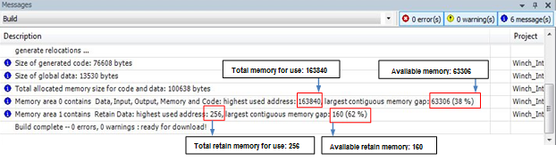
To optimize the memory consumption, avoid using function blocks and unnecessary variable definitions.
CPU limitation
The maximum execution load of the application is limited to 5 to 15% depending on the drive type. To know the actual load limit, contact your local ABB representative.
You can monitor the CPU load by checking the application load with parameter 7.11 Cpu usage. To know the load difference, compare CPU usage values with and without the application. Make sure that the difference value is not greater than the value limit. If the application exceeds the limit, the drive trips to the task overload fault 6481. The fault is registered to the event log of the drive and the fault-specific AUX code indicates the overloaded tasks (10 = task 1, 11 = task 2 and 12= task 3).
You can evaluate the total (task 1-3) CPU load using the parameters and “7.41 IEC Application Cpu load average”. For parameter descriptions, refer to ⮫ ACS880 Primary control program Firmware manual (AINLX) - Drive composer version.
Perform CPU load tests to make sure that the drive is capable of adequately running the application. Enable the required drive functions during the execution of the application. For example, motor control, communication modules, encoders, and so on.
Creating application loading package
This feature allows the user to create a loading package containing of an application program for ACS880 drive. To build a loading package when the tool is connected online to the drive, use the Automation Builder command “Create Boot Application”.
You can also create offline application loading package file without firmware version limit using premium license.
To create loading package with or without firmware restrictions in offline, you must have premium license.
Place the file to the corresponding project folder with the file name.
<project_name>_<device>_<application>.lp. Load the application loading packing using the Drive loader tool.
Application loading package functionality supports from AINFX 2.01 firmware version onwards.
Before loading the package, drive loader tool checks for the correct actual drive type and firmware version to load the package. It also checks for the correct drive application programming interface and the active programming license (N8010) in the target drive.
To include symbol data and source code to application wrap file and loading package using Automation Builder, follow these steps:
-
In the main menu of Automation Builder, go to “Project Project Settings”. Project settings dialog is displayed.
-
Click “Application loading settings ” and select the desired options.
Click add icon to add new firmware.
Enter the firmware details and click [Ok].
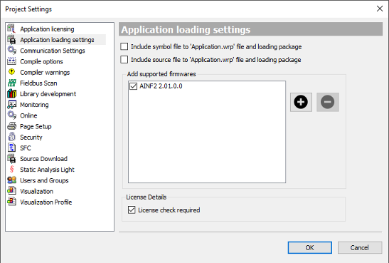
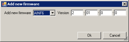
The added firmware is displayed in the “Application” loading settings.
Make sure that the application is working correctly with the added firmware. It is also possible to add more supported firmware versions to the application loading package.
To load the drive firmware, make sure the drive is connected to Drive Composer via USB cable. For more information, refer to ⮫ Drive composer start-up and maintenance PC tool user's manual.
Loading application to drive with “Drive Composer” – Drive firmware loader
To load the drive firmware, make sure the drive is connected to “Drive Composer” via USB cable. ⮫ 3AUA0000094606
-
1. Make sure that the drive is connected to “Drive Composer” via USB cable.
-
Power up the drive. Make sure that the motor is not running (inverter) or the unit is not operating (supply unit). If drive is connected via USB cable, Click “Connect”. drive.
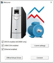
If drive is connected via a USB cable, “Drive Composer” automatically discovers the drive.
-
In main menu, click “Tools Drive firmware loader”.
The Firmware update window appears.
-
If you have connected through Ethernet cable or the “Drive Composer” in the Offline/Virtual Drives mode, and you open the firmware loader, a “FIRMWARE UPDATE” warning message appears. Click [OK].

-
Select the offline update tab and browse the application loading package file. To select the application loading package from your computer, click [Offline update], Browse the package and click [Select].
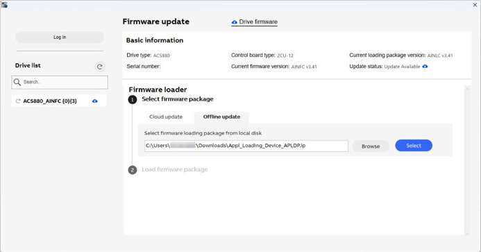
If you try to load a corrupted or invalid loading package file, the application displays an error message.

-
In firmware update window, Click [Next].

-
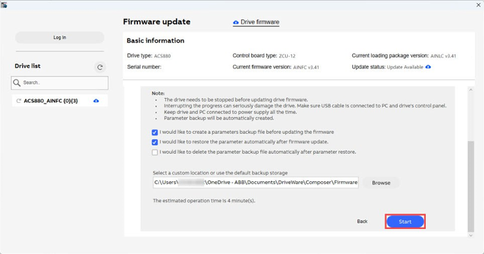
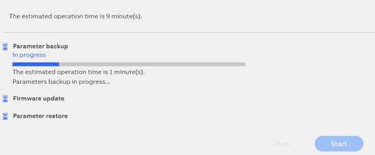
Select the desired check box if you want to create backup, restore parameters from backup file or delete the file automatically after parameter restore. Select the location to save the file if you want to create a backup. Click [Start].
-
Wait for the firmware to be loaded. The backup time can be more if you select the parameter backup option.
-
The installation successful page appears.

-
Click [Close].
Verify that the application is loaded to the drive. Refresh the drive in “Drive Composer”.
Confirm that the updated parameters using the “Drive Application Builder” are visible in the “Drive Composer”. Check the application name matches the latest name in the loading package file.
