


Starting a new project in the offline mode
The Guided Project Selection feature helps users create Drive projects in Automation Builder more efficiently. It provides an Offline Selection (Manual Configuration) mode for users configuring a project without hardware access.
The Offline Drive Selection includes descriptions and tooltips for easier decision-making and offers a hierarchical selection path:
-
Level 1: Drive family (ACS, DCS, HES, MV)
-
Level 2: Control board (ZCU, BCU, UCU, etc.)
-
Level 4: Firmware version
After starting Automation Builder programming environment, you can create a new project in the offline mode.
-
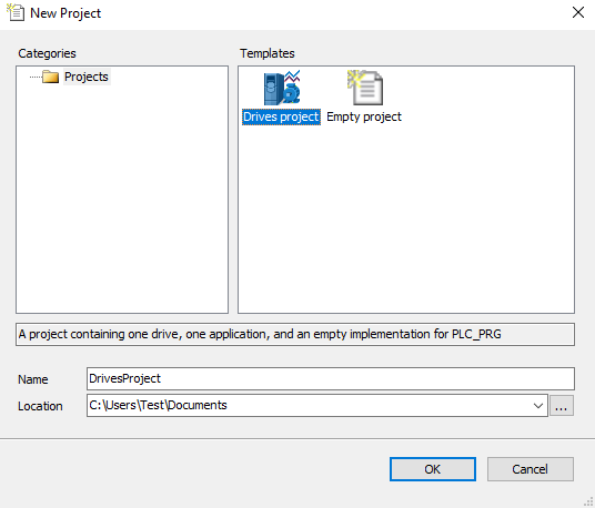
On the start page, click “New Project” or in the main menu, go to “File” and select “New Project”.
-
In the “New Project” dialog, select the Drive project template and click [OK]. You can rename the project in the“Name” field and select the desired location in the file system.
-
In the “New Project” dialog, select the type of control unit in the device list. You can select the category in the “Categories” to narrow down the device list.
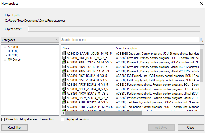
Check the control unit type of the target drive either from the unit itself from the hardware manual of drives or contact your local ABB representative.
-
After you confirm the selection Automation Builder generates the project structure automatically.
The device tree includes:
-
“PLC Logic”
-
“DriveInterface” for firmware signal and parameter mapping
-
Application (for example, you can add the following objects under “Application”)
-
Library Manager for installing function libraries
-
“ApplicationParametersandEvents” for creating user parameters and events
-
Program organization units (POUs)
-
Task Configuration module for defining in which task the POUs are executed
-
Text list
-
Symbol configuration
-
Global variable list
-
Data type units (DUT)
-
Updating project information
You can update company name and version number for the application program in the “Project Information” window. This information is visible in Drive Composer pro tool and ACS-AP-x control panel in the “System Info” display. It helps to identify the loaded application without the Automation Builder. You can also name the application from the application tool.
To update project information in Automation Builder, follow these steps:
-
In the main menu, go to “Project” and select “Project Information”.
-
In the “Project Information” dialog, go to “Summary” tab and update the desired information and click [OK].
The updated project information is not loaded to the target application. Further steps explain how to copy this information to the application information fields.
-
In the device tree, right click “Applications” and select “Properties”. “Properties” dialog is displayed.
-
Click “Information” tab and click “Reset to values from project information ”. Confirm with “OK”.
The Automation Builder version and project identification code are registered automatically.
Writing a program code
A program organization unit (POU) is a unit, object or area where you can write the program code. The units can be created either directly under the “Application” in the device tree or in a separate POUs window (“View POUs” or click “POUs ” in the lower left corner).
The “POU” includes a declaration part (the upper window) and a program code part (the lower window).
Continuous function chart (CFC) program
The following sections show how to create a new project in the CFC implementation language.
Adding elements
-
In the device tree, expand “Application” and select “xxx(PRG)”.
-
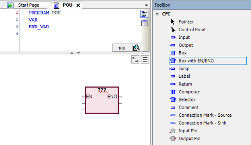
In the main menu, click “View ” and select “ToolBox”.
“ToolBox” components are displayed and are used to add a CFC scheme.
-
If an empty “ToolBox” list is already displayed on the right side of the window, double-click the xxx (PRG) to display the “Toolbox” and the “POU” window.
-
To add “SEL” and “AND” elements (logic operators, functions), use the box element in the “ToolBox” list.
-
In the “ToolBox” list, drag and drop the “Box” into the program code area.
-
Enter the name of the function or operand in the “ ??? ” field.
You can also use “Input Assistant” to find the function, keyword and operator. To start “Input Assistant”, click the button or press F2.
The number in the upper right corner of the white box indicates the execution order of the function.
-
Right-click on input or output element and select “Negate” to invert.
Setting the execution order of the elements
Each element has its own execution order. The number in the upper right corner of the element indicates the sequence in which the elements in a CFC network are executed in the online mode. The processing starts from the element with the lowest number, that is 0. Note that the sequence influences the result and are changed in certain cases.
You can set the execution order of each element using “Set Execution Order” and define the number.
Establishing online connection to the drive
The Automation Builder communication gateway handles communication between Automation Builder and the drive. The gateway is a software component that starts automatically at the powerup of the PC after installing Automation Builder.
Before starting with the communication setup, follow the pre-requisites listed below.
Pre-requisites:
-
Connect the PC to a drive through USB port of the ACS-AP-x control panel using a standard USB data cable (USB Type A <-> USB Type Mini-B).
For information on making the control panel to PC USB connection, refer to ⮫ ACS-AP-I, -S, -W and ACH-AP-H, -W Assistant control panels user's manual
-
Make sure the ACS-AP-x USB driver is installed.
For installation procedure, refer to ⮫ Drive composer start-up and maintenance PC tool user's manual
-
Make sure the drive has application programming license N8010. To check license information in Drive Composer pro and in ACS-AP-x control panel, go to “System info Licenses”
To establish online connection to the target drive after defining the device type, follow these steps:
-
In the device tree, double-click “Device” (ACS880_AINF_ZCU12_14_M_V3_5) and select “ABB Drives communication settings”.
PC name is displayed by default.
-
Check that the USB cable is connected to the USB connector of the ACS-AP-x control panel and the drive is powered.
-
Double-click on first node (node with host name) or click “Scan network ” to search the target device.
Filter Target ID displays only devices that are of the same type as the device selected in the devices window.

-
Double-click the device or click [Set as active Path].
If the drive has appropriate license code, the selected device is set as active path and is ready for downloading a program to the drive.
If the drive does not have the required license code, the selected device is displayed with no license.
Restarting DriveDA process
You can recover from issues when scanning for drives in Automation Builder using the [Refresh] button. In some cases, the DriveDA process may hang or fail to list available drives. It is not necessary to manually stop DriveDA using Task Manager, the [Refresh] button automates this process safely and reliably. You can use the [Refresh] button in the following situations:
-
If scanning for drives hangs or shows no results.
-
If drive communication appears unresponsive.
-
If you want to restart DriveDA without closing Automation Builder.
The [Refresh] button is available on the right side in the following locations:
-
Drives communication editor
-
“Create boot application on multiple devices” window
-
“Unlock communication” window
-
“Source download to Drive” window
When you click the [Refresh] button, Automation Builder will:
-
Check whether Drive Composer pro is currently running.
If Drive Composer pro is NOT running : DriveDA is restarted automatically.
If Drive Composer pro IS running: a warning is shown, as the restart may interrupt ongoing operations. You can choose whether to proceed or cancel.
-
Stop the DriveDA process safely.
-
Restart DriveDA.
-
Rescan connected drives.