


FEA-03
The FEA-03 F-series Extension adapter is used to locate additional F-series modules like FIO-01, FIO-11, FAIO-01 or FDIO-01. The FEA-03 module contain 2-slots with 2-switches each. You can add FIO-01, FIO-11, FAIO-01 or FDIO-01 modules to the slots of the control board or FEA-03 module. The application programming supports 7-extension I/O modules.
⮫ ACS880 Primary control program Firmware manual (AINLX)
For example, the figure below illustrates the maximum configuration of F-Series modules on the Control board (ZCU) and FEA-03 adapters. It contains 3-firmware and 7-program modules. Node numbers 1, 2, 3 are on control board slot 1, 2, 3 and the remaining node numbers are FEA-modules and their node numbers are defined by F-Series module switch.
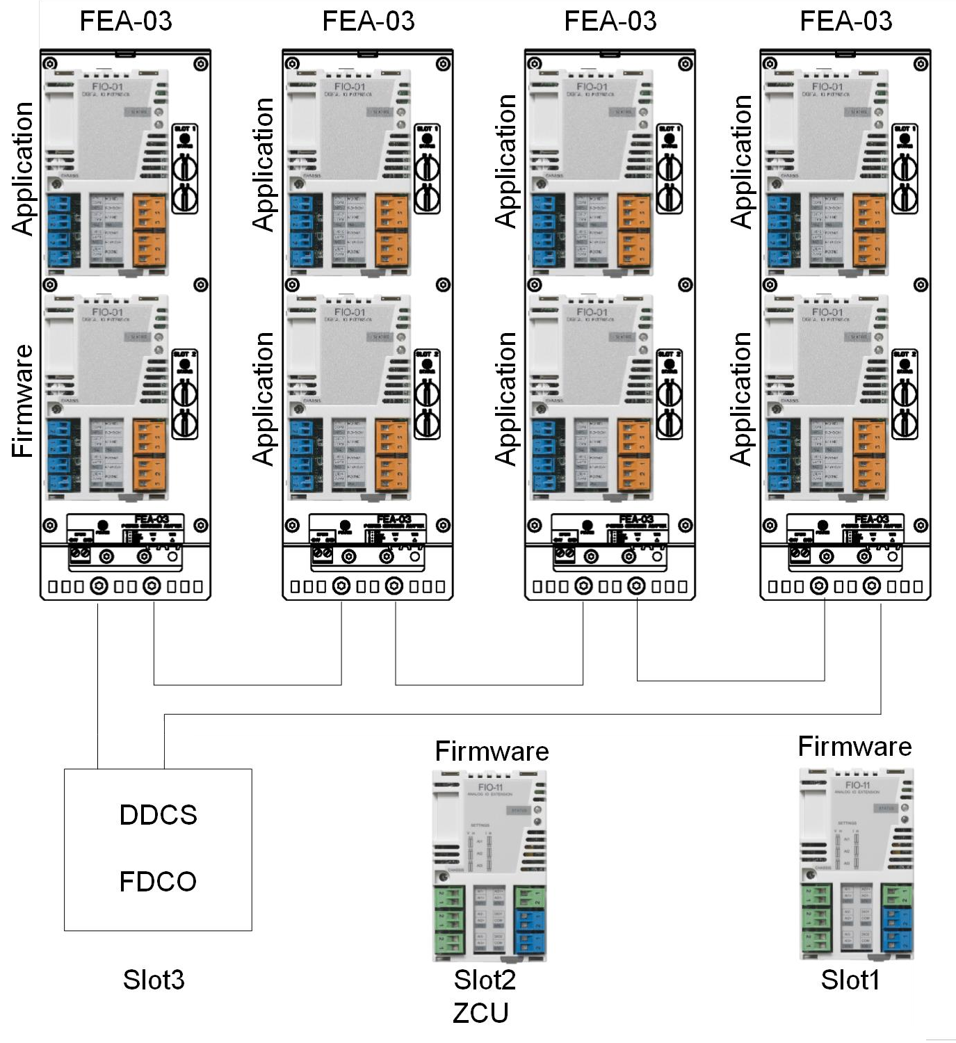
Node numbers
The node numbers 1…3 are reserved for extension I/O modules that are placed on the slots of control board and the other node numbers can be used for modules in FEA object.
The upper switch defines the first digit and the lower switch defines the second digit of the node ID. For example, in case of node address 6, turn the lower switch to 6 and check that the upper switch points to 0.
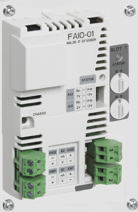
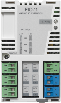
Selecting input signal type
You can select the unit (mA or V) of an analog signal by sliding the switches of FIO module next to the input either up for current signal or down for voltage signal.
FDCO
In FDCO adapter, select the channel number based on the used slot. Communication slot for FDCO adapter is defined by parameter 60.41 Extension adapter com port based on the used slot and channel.
For the descriptions of parameter, refer to⮫ ACS880 Primary control program Firmware manual (AINLX)
For example, if FDCO adapter is placed on slot 2 and channel A is used, then slot2A is selected for Extension adapter com port.
For further details, refer to ⮫ FDCO-01/02 DDCS communication modules user's manual
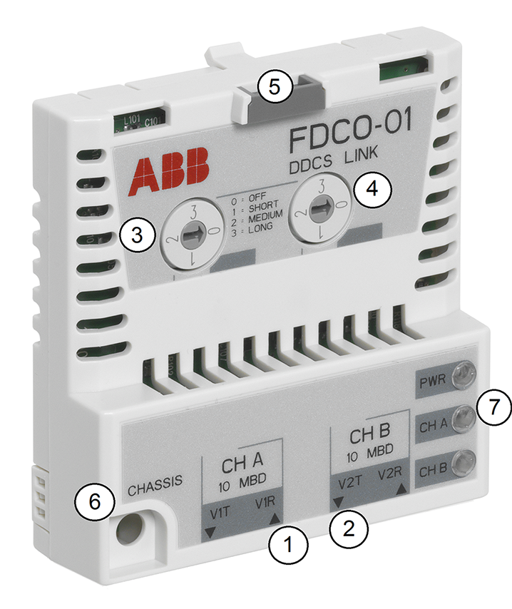
1
Connector for channel A
2
Connector for channel B
3
Selector for channel A
4
Selector for channel B
5
Lock
6
Mounting screw
7
LED
-
Extension I/O in drive application program