


During the power ON procedure, the module initializes automatically. All LEDs (except the channel LEDs) are ON during this time.
|
LED |
State |
Color |
LED = OFF |
LED = ON |
LED flashes |
|
|---|---|---|---|---|---|---|
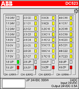 |
Inputs/outputs C0 ... C23 |
Digital input or digital output |
Yellow |
Input/output = OFF |
Input/output = ON 1) |
-- |
|
UP |
Process supply voltage 24 V DC via terminal |
Green |
Process supply voltage is missing |
Process supply voltage OK |
-- |
|
|
CH-ERR1 |
Channel error, error messages in groups (digital inputs/outputs combined into the groups 1, 2, 3, 4) |
Red |
No error or process supply voltage is missing |
Severe error within the corresponding group |
Error on one channel of the corresponding group (e.g. short circuit at an output) |
|
|
CH-ERR2 |
Red |
|||||
|
CH-ERR3 |
Red |
|||||
|
CH-ERR4 |
Red |
|||||
|
CH-ERR 2) |
Module error |
Red |
-- |
Internal error or module not configured |
-- |
|
|
1) Indication LED is ON even if an input signal is applied to the channel and the supply voltage is off. In this case the module is not operating and does not generate an input signal. |
||||||
|
2) All of the LEDs CH-ERR1 to CH-ERR4 light up together |
||||||