


-
8 digital inputs 24 V DC
-
8 digital outputs 24 V DC, 0.5 A max.
-
8 configurable digital inputs/outputs 24 V DC, 0.5 A max.
-
Cam switch functionality (see also Extended Cam Switch Library)
-
Extended Cam switch functionality *)
(see also Extended Cam Switch Library)
-
Module-wise galvanically isolated
-
Expandability with up to 10 S500 I/O modules *)
*) Applicable for device index C0 and above.
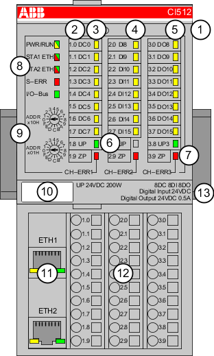
1
I/O bus
2
Allocation between terminal number and signal name
3
8 yellow LEDs to display the signal states of the digital configurable inputs/outputs (DC0 ... DC7)
4
8 yellow LEDs to display the signal states of the digital inputs (DI0 ... DI7)
5
8 yellow LEDs to display the signal states of the digital outputs (DO0 ... DO7)
6
2 green LEDs to display the supply voltage UP and UP3
7
3 red LEDs to display errors (CH-ERR1, CH-ERR2, CH-ERR3)
8
5 System LEDs: PWR/RUN, NET, DC, S-ERR, I/O-Bus
9
2 rotary switches (reserved for future extensions)
10
Label
11
Ethernet interfaces (ETH1, ETH2) on the terminal unit
12
Terminal unit
13
DIN rail