


Differential inputs are very useful, if analog sensors are used which are remotely non-isolated (e.g. the minus terminal is remotely grounded).
The evaluation using differential inputs helps to considerably increase the measuring accuracy and to avoid ground loops.
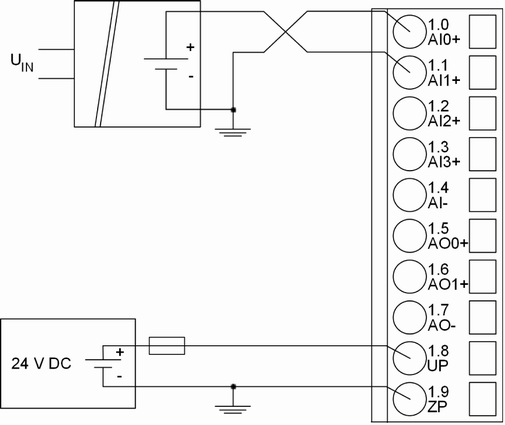
With differential input configurations, two adjacent analog channels belong together (e.g. the channels 0 and 1). In this case, both channels are configured according to the desired operating mode. The lower address must be the even address (channel 0), the next higher address must be the odd address (channel 1). The converted analog value is available at the higher address (channel 1).
The analog value is calculated by subtraction of the input value with the higher address from the input value of the lower address.
The converted analog value is available at the odd channel (higher address).

CAUTION
Risk of faulty measurements!
The negative pin at the sensors must not have too big a potential difference with respect to ZP (max. ± 1 V).
Make sure that the potential difference never exceeds ± 1 V.
|
Voltage |
0 V ... 10 V |
With differential inputs, 2 channels used |
|
Voltage |
-10 V ... +10 V |
With differential inputs, 2 channels used |
To avoid error messages from unused analog input channels, configure them as "unused".