


The function module CD522 can be connected to the following devices via the I/O bus connector:
-
CS31 bus module DC551-CS31
-
AC500 CPU
-
OtherAC500 I/O devices.
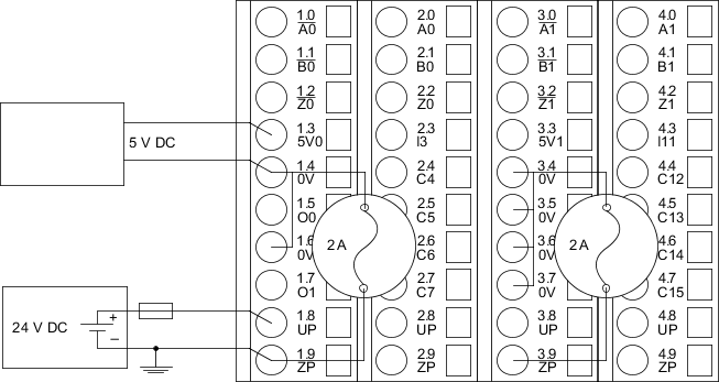
The connection is carried out by using the 40 terminals of the terminal unit TU515/TU516.
⮫ “TU515, TU516, TU541 and TU542 for I/O modules”
|
Terminal |
Signal |
Description |
|---|---|---|
|
1.0 |
/A0 |
Inverted input signal A of encoder 0 |
|
1.1 |
/B0 |
Inverted input signal B of encoder 0 |
|
1.2 |
/Z0 |
Inverted input signal Z of encoder 0 |
|
1.3 |
5V0 |
+5 V DC power supply output 0 for sensors |
|
1.4 |
0V |
0 V reference input |
|
1.5 |
O0 |
Output signal of the fast output O0 |
|
1.6 |
0V |
0 V reference input |
|
1.7 |
O1 |
Output signal of the fast output O1 |
|
1.8 |
UP |
Process voltage UP (24 V DC) |
|
1.9 |
ZP |
Process voltage ZP (0 V DC) |
|
2.0 |
A0 |
Input signal A of encoder 0 |
|
2.1 |
B0 |
Input signal B of encoder 0 |
|
2.2 |
Z0 |
Input signal Z of encoder 0 |
|
2.3 |
I3 |
Input signal I3 (standard input) |
|
2.4 ... 2.7 |
C4 ... C7 |
Signal of the configurable digital input/output C4 ... C7 |
|
2.8 |
UP |
Process voltage UP (24 V DC) |
|
2.9 |
ZP |
Process voltage ZP (0 V DC) |
|
3.0 |
/A1 |
Inverted input signal A of encoder 1 |
|
3.1 |
/B1 |
Inverted input signal B of encoder 1 |
|
3.2 |
/Z1 |
Inverted input signal Z of encoder 1 |
|
3.3 |
5V1 |
+5 V DC power supply output 1 for sensors |
|
3.4...3.7 |
0V |
0 V reference input |
|
3.8 |
UP |
Process voltage UP (24 V DC) |
|
3.9 |
ZP |
Process voltage ZP (0 V DC) |
|
4.0 |
A1 |
Input signal A of encoder 1 |
|
4.1 |
B1 |
Input signal B of encoder 1 |
|
4.2 |
Z1 |
Input signal Z of encoder 1 |
|
4.3 |
I11 |
Input signal I11 (standard input) |
|
4.4 ... 4.7 |
C12 ... C15 |
Signal of the configurable digital input/output C12 ... C15 |
|
4.8 |
UP |
Process voltage UP (24 V DC) |
|
4.9 |
ZP |
Process voltage ZP (0 V DC) |
The internal power supply voltage for the module's circuitry is carried out via the I/O bus (provided by a communication interface module or a processor module). Thus, the current consumption from 24 V DC power supply at the terminals L+/UP and M/ZP of the CPU/communication interface module increases by 2 mA per CD522.
The external power supply connection is carried out via the UP (+24 V DC) and the ZP (0 V DC) terminals.

WARNING
Removal/Insertion under power
The devices are not designed for removal or insertion under power. Because of unforeseeable consequences, it is not allowed to plug or unplug devices with the power being ON.
Make sure that all voltage sources (supply and process voltage) are switched off before doing the following:
-
Connect or disconnect any signal or terminal block.
-
Remove, mount or replace a module.
Disconnecting any powered devices while energized in a hazardous location could result in an electric arc, which could create a flammable ignition resulting in fire or explosion.
Make sure that power is removed and that the area has been thoroughly checked to ensure that flammable materials are not present prior to proceeding.
The devices must not be opened when in operation. The same applies to the network interfaces.

NOTICE
Risk of damaging the PLC modules!
Overvoltages and short circuits might damage the PLC modules.
-
Make sure that all voltage sources (supply voltage and process supply voltage) are switched off before you begin with operations on the system.
-
Never connect any voltages or signals to reserved terminals (marked with ---). Reserved terminals may carry internal voltages.
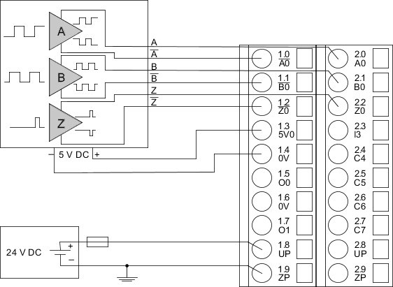
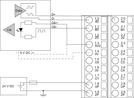
Connection of encoders with differential RS-422 signal
The encoder is powered by the 5 V power supply which is integrated in CD522.
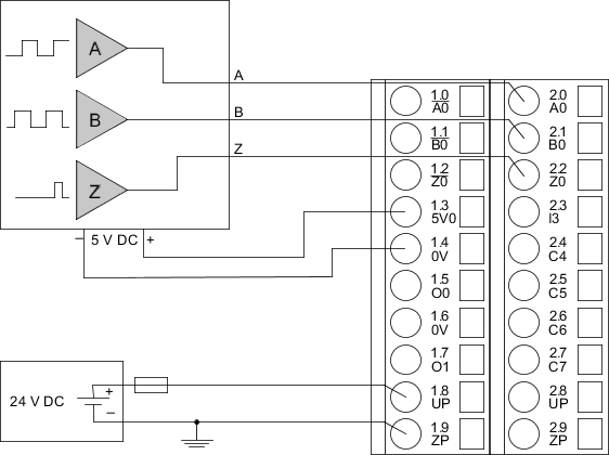
Connection of encoders with 5 V TTL signal
The encoder is powered by the 5 V power supply which is integrated in the CD522.
Connection of encoders with 24 V totem pole signal
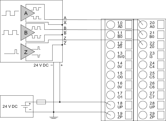
The wires A, B and Z need not to be connected to the module. They are left open.
When using different power supplies for the encoder device and the CD522, make sure that the reference potentials of both power supplies are interconnected.
Connection of encoders with 1 Vpp sine signal
The encoder is powered through the 5 V power supply which is integrated in the CD522.

Connection of absolute encoders with SSI interface and differential RS-422 signal
The encoder is powered by the 5 V power supply which is integrated in the CD522.
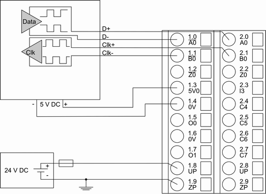
Connection of absolute encoders with an SSI interface and an optocoupler interface at CLK input
The encoder can optionally be powered by the 5 V power supply which is integrated in the CD522.
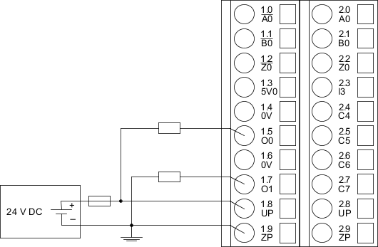
Connection of output loads to the PWM/Pulse putputs
NOTICE
Risk of damaging the module
The PWM outputs have no protection against reverse polarity.
NOTICE
Risk of damaging the module
The two 5 V outputs have no protection against reverse polarity.
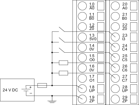
Connection of standard inputs/outputs
Proceed with the inputs/outputs I11 and C12 ... C15 in the same way.
Connection of sensors with frequency outputs
Proceed with the A0, B0, A1, B1 and Z1 in the same way.
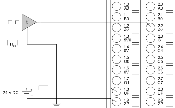
NOTICE
Risk of malfunctions!
The edges of a signal must be strong enough (0.4 V/µs) to be recognized correctly by the module.
Put a 1 kW resistor between 0 V and the Z terminal when using a standard output as time generator.
Connection of sensors to the 5 V power supply
Proceed with the 5 V power supply 1 in the same way.
Each 5-V-power supply provides a current of 100 mA max. It is possible to parallel both integrated power supplies. In this case, the max. current is 200 mA.
NOTICE
Risk of damaging the module
The integrated 2 A fuse cannot be replaced. If it blows, the module must be replaced.
Ensure that the current per 0 V connection does not exceed 0.5 A.
NOTICE
Risk of damaging the module
The two 5 V outputs have no protection against reverse polarity.