


For a detailed description of the mounting, disassembly and connection of the module, please refer to the ⮫ installation instructions.
The connection is carried out by using a removable 9-pin and 11-pin terminal block. These terminal blocks differ in their connection system (spring terminals or screw terminals, cable mounting from the front or from the side). The terminal blocks are not included in the module's scope of delivery and must be ordered separately.
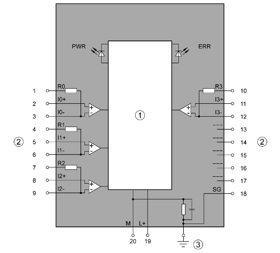
1
Logic - I/O bus interface
2
Analog inputs
3
Functional earth connection
|
Terminal |
Signal |
Description |
|---|---|---|
|
1 |
R0 |
Burden resistor for input signal 0 for current sensing |
|
2 |
I0+ |
Positive pole of input signal 0 |
|
3 |
I0- |
Negative pole of input signal 0 |
|
4 |
R1 |
Burden resistor for input signal 1 for current sensing |
|
5 |
I1+ |
Positive pole of input signal 1 |
|
6 |
I1- |
Negative pole of input signal 1 |
|
7 |
R2 |
Burden resistor for input signal 2 for current sensing |
|
8 |
I2+ |
Positive pole of input signal 2 |
|
9 |
I2- |
Negative pole of input signal 2 |
|
10 |
R3 |
Burden resistor for input signal 3 for current sensing |
|
11 |
I3+ |
Positive pole of input signal 3 |
|
12 |
I3- |
Negative pole of input signal 3 |
|
13 |
--- |
Reserved |
|
14 |
--- |
Reserved |
|
15 |
--- |
Reserved |
|
16 |
--- |
Reserved |
|
17 |
--- |
Reserved |
|
18 |
SG |
Shield grounding |
|
19 |
L+ |
Process voltage L+ (24 V DC) |
|
20 |
M |
Process voltage M (0 V DC) |
The internal power supply voltage for the module's circuitry is carried out via the I/O bus (provided by a communication interface module or a CPU). Thus, the current consumption from 24 V DC power supply at the terminals L+/UP and M/ZP of the CPU/communication interface module increases by 5 mA per AI561.
The external power supply connection is carried out via the L+ (+24 V DC) and the M (0 V DC) terminals. The M terminal is interconnected to the M/ZP terminal of the CPU/communication interface module.

NOTICE
Risk of imprecise and faulty measurements!
Analog signals may be severely distorted due to external electromagnetic interference.
When the length of the connection cable exceeds 20 m, a shielded and grounded cable must be used. When the shield is grounded at both ends, an independent low-impedance equipotential connection should be provided to avoid high potential differences between interconnected devices.
NOTICE
Risk of damaging the PLC modules!
The PLC modules must not be removed while the plant is connected to a power supply.
Make sure that all voltage sources (supply and process voltage) are switched off before you do the following:
-
Connect or disconnect any signal or terminal block.
-
Remove or replace a module.
NOTICE
Risk of damaging the PLC modules!
Overvoltages and short circuits might damage the PLC modules.
-
Make sure that all voltage sources (supply voltage and process supply voltage) are switched off before you begin with operations on the system.
-
Never connect any voltages or signals to reserved terminals (marked with ---). Reserved terminals may carry internal voltages.
The module provides several diagnosis functions.
The following figure is an example of the internal construction of the analog input AI0. The analog inputs AI1 ... AI3 are designed in the same way.


CAUTION
Risk of damaging the analog input!
The 250 W input resistor can be damaged by overcurrent.
Make sure that the current through the resistor never exceeds 30 mA.
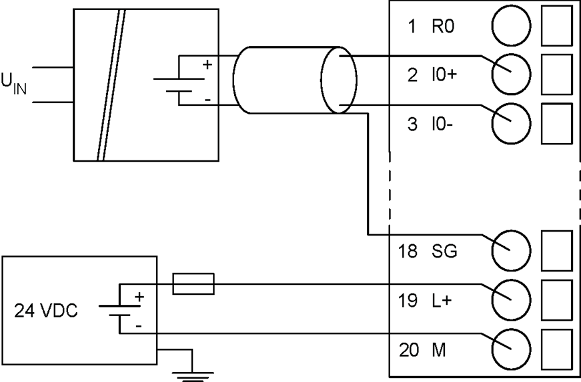 |
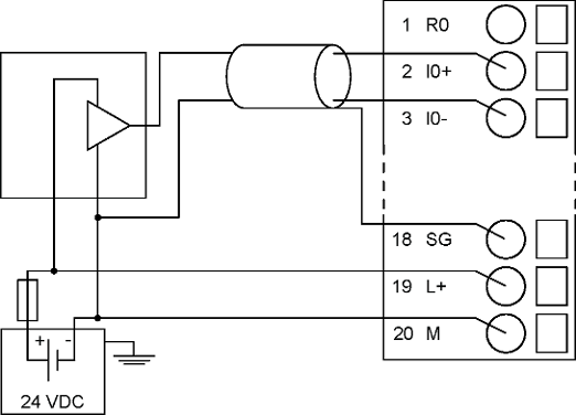 |
|
Connection of active-type analog sensors (voltage) |
Connection of passive-type analog sensors (voltage) |
|
Connection of active-type analog sensors (voltage) |
Connection of passive-type analog sensors (voltage) |
|---|---|
|
-2.5 V ... 2.5 V |
-2.5 V ... 2.5 V |
|
-5 V ... 5 V |
-5 V ... 5 V |
|
0 V ... 5 V |
0 V ... 5 V |
|
0 V ... 10 V |
0 V ... 10 V |
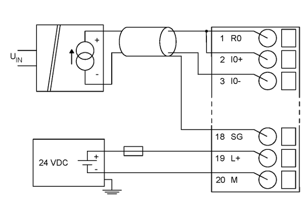 |
 |
|
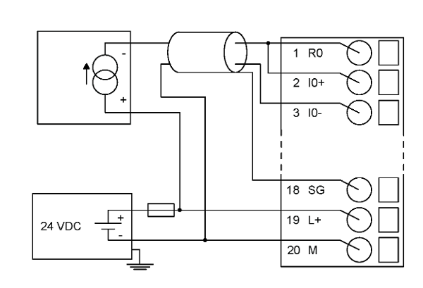
Connection of active-type analog sensors (current) |
Connection of passive-type analog sensors (current) |
|
Connection of active-type analog sensors (voltage) |
Connection of passive-type analog sensors (voltage) |
|---|---|
|
4 mA ... 20 mA |
4 mA ... 20 mA |
|
0 mA ... 20 mA |