


Differential inputs are very useful if analog sensors are used which are remotely non-isolated (e.g. the minus terminal is remotely grounded).
The use of differential inputs helps to considerably increase the measuring accuracy and to avoid ground loops.
With differential input configurations, two adjacent analog channels belong together (e.g. the channels 0 and 1). In this case, both channels are configured according to the desired operating mode. The lower address must be the even address (channel 0), the next higher address must be the odd address (channel 1). The converted analog value is available at the higher address (channel 1).
The analog value is calculated by subtraction of the input value with the higher address from the input value of the lower address.
The converted analog value is available at the odd channel (higher address).

CAUTION
Problems with the common-mode input voltages of the involved analog inputs
The ground potential at the sensors must not have too large a potential difference with respect to ZP (max. ±1 V within the full signal range).
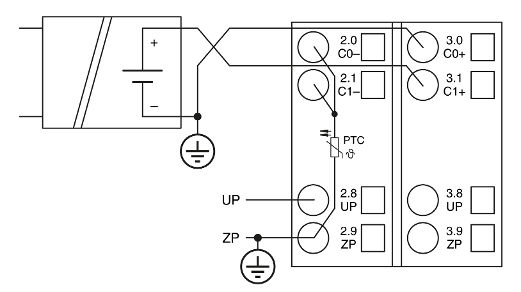
The negative pole of the sensor must be grounded next to the sensor.
|
Voltage |
0 V ... 10 V |
with differential inputs, 2 channels used |
|
Voltage |
-10 V ... +10 V |
with differential inputs, 2 channels used |
In order to avoid error messages or long processing times, it is useful to configure unused analog input channels as "unused".