


The following describes how to create an “IEC 61850 Server” and configure the IEC 61850 data model with logical nodes, data objects and data attributes which can be connected to global variables in the IEC 61131 application. Starting point is a new or existing project with an AC500 CPU.
Add IEC 61850 Server
Add an “IEC 61850 Server” object below Ethernet port “ETH1” or “ETH2”, depending on which IP address the MMS server should use. The IP addresses of “ETH1” and “ETH2” are configured with the “IP-Configuration” tool.
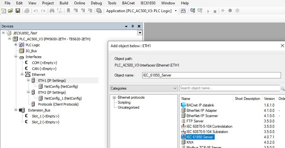
GOOSE Publisher and Subscriber is independent of the IP address. Instead, the Ethernet MAC addresses must be configured in GOOSE Publisher and/or Subscriber. Even if only GOOSE is configured like in example B, an “IEC 61850 Server” is required, which can be placed below any Ethernet port.
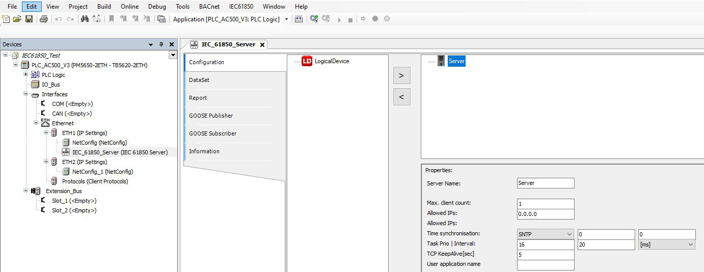
The properties of the “IEC 61850 Server” can be configured. For basic functionality, the default values can be used.
|
Property |
Description |
|---|---|
|
Server Name |
Name of the server. |
|
Max.client count |
The maximum number of clients that can connect to the IED, possible values: 1, 2, 3, 4, 5 |
|
Allowed IPs |
Allowed IPs for clients 1...5. Default is 0.0.0.0, whereby an IP address that equals 0.0.0.0 means that no IP address validity test will take place. If more than one client connection was selected above, additional IPs must be configured for each one. As soon as an IP address is parameterized with 0.0.0.0, testing for all connected clients is deactivated. |
|
Time synchronisation |
Selection: SNTP SNTP (only possible option): (S)NTP time synchronization The following values should only be used if the PLC time is interpreted as UTC time: 1. Input field Time zone: Offset between Greenwich (GMT)- and the local time (for Germany 1 h, for example). The value is limited between -12 and + 14. 2. Input field: DLS Mode: Day light saving. Possible values:
|
|
Task Prio I Interval |
Task, which will be generated by Generate IEC 61850 code: 1. Input field - entry of the priority, 2. Input field - entry of the interval in ms. |
|
TCP KeepAlive [sec] |
The KeepAlive is to check the connection to the client. |
|
User application name |
Enter the name of the user application for optimized GOOSE performance. The IEC 61850 task will execute in the following order: 1. GOOSE Subscriber 2. User application 3. GOOSE Publisher and MMS reporting If this field is empty, the user application (step 2) will not be called by the IEC 61850 task, but by the standard task. Two tasks are asynchronous and might lead to slower performance. |
The server is the root object for creating the IEC 61850 data model consisting of “LogicalDevice”, logical nodes, data objects and data attributes.
Add LogicalDevice
Add the “LogicalDevice” by selecting it in the left window and inserting it below the server with the arrow button “>”.
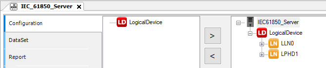
Following properties of the logical device can be configured.
|
Property |
Description |
|---|---|
|
Device Name |
Name of the LogicalDevice |
Add logical nodes
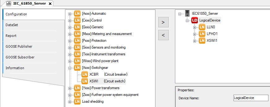
Two standard logical nodes (“LLN0” and “LPHD1”) are added automatically. Further logical nodes (e.g. “XSWI”) can be added by selecting them from the left window and inserting them below the logical device with the arrow button “>”.
Following properties of the logical device can be configured.
|
Property |
Description |
|---|---|
|
Node prefix |
Optional prefix for the selected LNC instance. The prefix is put in front of the LN name in the server tree. |
|
Logical Node index |
Index to differentiate between several instances of the same logical node type. It is assigned automatically with increasing order, starting with 1. If it is changed manually, duplicates should be avoided. |
Add data objects
Logical nodes are instantiated with their mandatory data objects “DO”. Optional data objects can be added by selecting them in the left window and inserting them below the logical node with the button “>”.
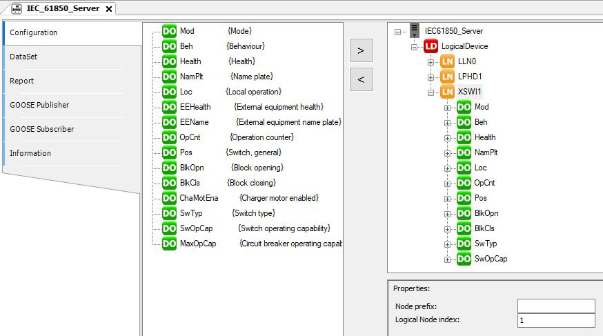
Data objects have no properties to be configured.
Add data attributes and mapping to variables
Data objects are instantiated with their mandatory data attributes “DA”. Optional data attributes can be added by selecting them in the left window and inserting them below the data object with the button “>”.
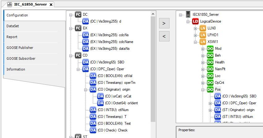
Data attributes can be mapped to variables in the IEC 61131 application by the following properties.
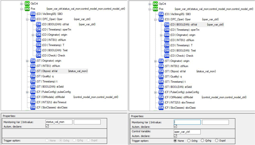
|
Property |
Description |
|---|---|
|
Monitoring Var I Initvalue |
Name of the monitoring variable, which can be written by AC500 and read by an IEC 61850 client, for example the status stVal of a switch position / An initial value can be defined optionally. |
|
Control Variable |
Name of the control variable which can be written from an IEC 61850 client and read by AC500, for example a switch command Oper.ctlVal. |
|
Autom. declare |
By activating the Autom. declare checkbox the variable is declared by the IEC 61850 configurator and stored in the IEC61850_Generated_GVL (of the IEC61850 generated POUs folder) after generate code of the IEC 61850 server. If it is not declared automatically, the variable must be declared by the user. Instead, an IO point can be chosen as monitoring or control variable. |
|
Trigger options |
With the trigger options you select the events which might trigger a report. The selected trigger option is displayed in the status bar. |