


With PS5611-Motion different motion control system structures are possible. Independent of the system structure a typical motion control application consists of the following system elements:
-
An application program which contains PLCopen function blocks that defines the general application behavior and logics.
-
A profile generator which generates a position profile based on the dynamic specifications of the application program to guide the axis to the desired positions.
-
A position control loop which outputs a speed reference signal to minimize the following error.
To achieve the best system structure for an application these components can be separated into different devices. Each type of structure has its own kind of interface and type of signals which need to be transferred between the interacting devices.
All shown motion control system structures (Central motion control with or without position control loop) can be combined together in the same application program for a motion control project.
With the function blocks of motion library a motion control profiler can be used inside the PLC. As shown in the following figure it is needed to provide the actual position of the drive. The output can be either a position or a velocity reference signal. The used output signal will then be used to move the axis in the desired way.
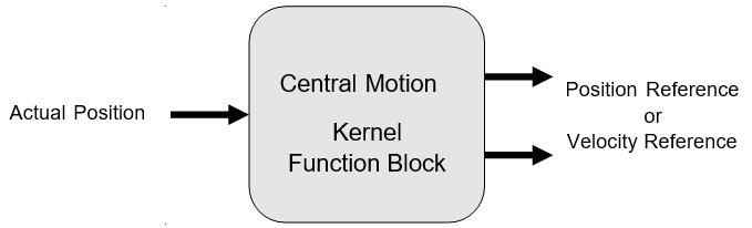
There are 2 possibilities to send a reference value to the drive:
-
When the position control loop is closed by the PLC by a CMC_Basic_Kernel function block, the output Speed_Reference should be connected to the drive. The value of Speed_Reference can be scaled with the axis parameters Max_Rpm and Ref_Max.
-
When the position control loop is closed by the drive, the output Position_Reference should be connected to the drive. The unit for the output Position_Reference is incremented as well as the input Drive_ActualPosition.
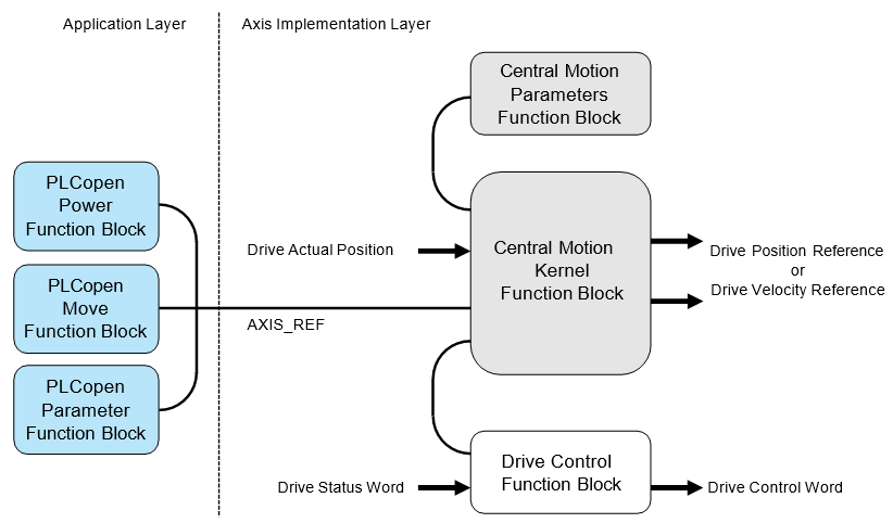
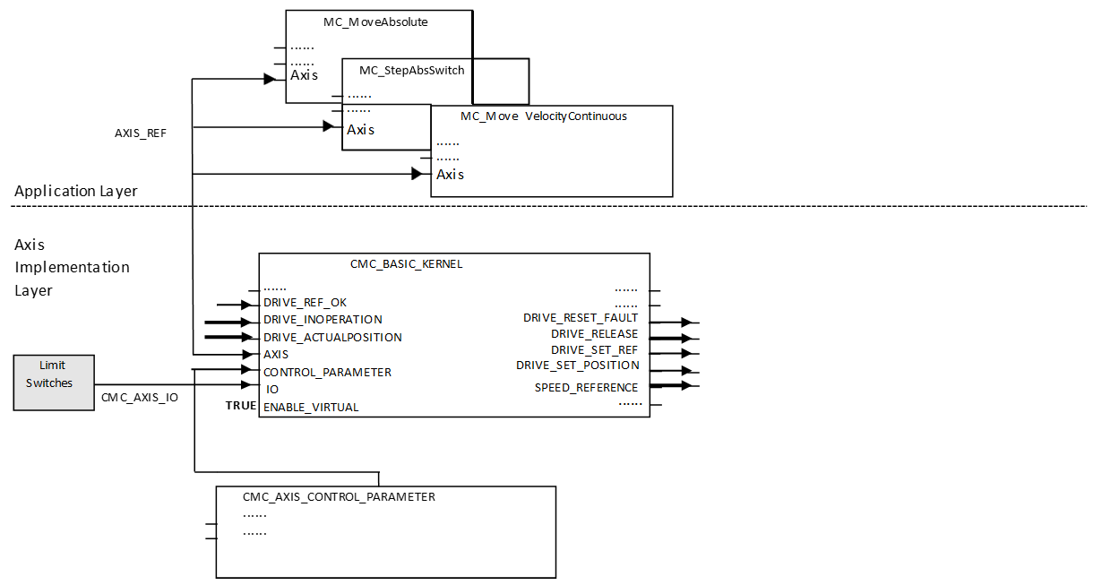
In general the programming of a machine consists of two layers as shown in the figure above.
In the application layer function blocks according to PLCopen motion control are used to program the application sequences with all necessary types of movements and administrational commands. Due to the standard PLCopen motion control this can be reused in any other machine programs that used PLCopen function blocks.
The axis implementation layer is responsible for the execution of the commands from the application layer and can be programmed for each axis in a different way depending on the used hardware components.
|
Library |
Content |
|---|---|
|
ABB_MotionControl_AC500.library |
Kernel function block, Parameters function block, Axis Simulation function block |
|
Data types for AC500 motion control |
|
|
Motion control function blocks according to PLCopen |
For a central motion axis implementation the use of the function blocks CMC_Basic_Kernel and CMC_Axis_Control_Parameter are mandatory.
The library design is independent from any bus architecture or any specific drive features.
Example for a possible system architecture
|
System |
Velocity reference |
Position feedback |
|---|---|---|
|
System A |
Output via analog output channel as voltage or current |
From incremental encoder connected to CD522 I/O module |
|
System B |
Output via EtherCAT network |
Input via EtherCAT network |
|
System C |
Output as frequency signal of CD522 I/O module |
From incremental encoder connected to CD522 I/O module |
|
System D |
Output via PROFINET IO network |
Input via PROFINET IO network |
|
System E |
Output via PTO & PWM channel in AC500-eCo |
Input via either encoder (included in onboard IO), or the PTO or PWM pulse count. |
In case the velocity reference value is used from the kernel function block the position control loop is closed inside the drive. In this case, it is necessary to adjust the related parameters from the parameters function block. When the position reference will be used the position control loop is closed inside the drive. In this case, the internal control loop is just used to monitor the position and velocity.
When the position reference is used for the drive the following aspects have to be taken care of:
-
It is necessary to use a real time fieldbus, like EtherCAT.
-
The PLC cycle has to be synchronized to the fieldbus cycle.
-
The task calculation times may not exceed the used cycle time.
The drive’s status should be managed by a specialized function block that supports the used type of drive as shown in the figure above. The kernel function block is the main function block which is needed to operate an axis with PLC-based motion control. It must be used with the parameter function block which is the interface to input parameters which are used to setup the axis.
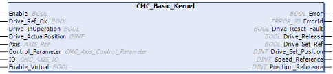
The drive has to be accessed outside the CMC_Basic_Kernel function block. Actual values and reference values might be transferred by a synchronized fieldbus or by I/Os. The function block CMC_Basic_Kernel has to be called every cycle and at least once before any function block MC or MCA is activated.
The following figure shows an example with an axis simulation. The main data signals are drawn in bold lines. Here, the drive will receive a speed reference signal which means that the position control loop is closed inside the PLC by the central motion function blocks. The time behavior of the simulated drive can be set by the parameter T1 at the axis simulation function block. If the time constant is to slow and the axis parameter Control_Time is too short the simulation axis will run into instability – like a real drive. Sample values⮫ “How to use the axis simulation”
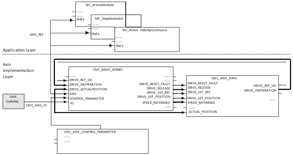
A different option to create a virtual or simulated axis is to engage the Enable_Virtual input at CMC_Basic_Kernel. This virtual axis will follow the speed reference without additional delay, whereas the CMC_Axis_Simu creates a first order delay.
The following figure shows an example with a CiA402 drive on an EtherCAT network. The main data signals are drawn in bold lines. Here, the drive will receive a position reference signal which means that the position control loop is closed inside the drive.
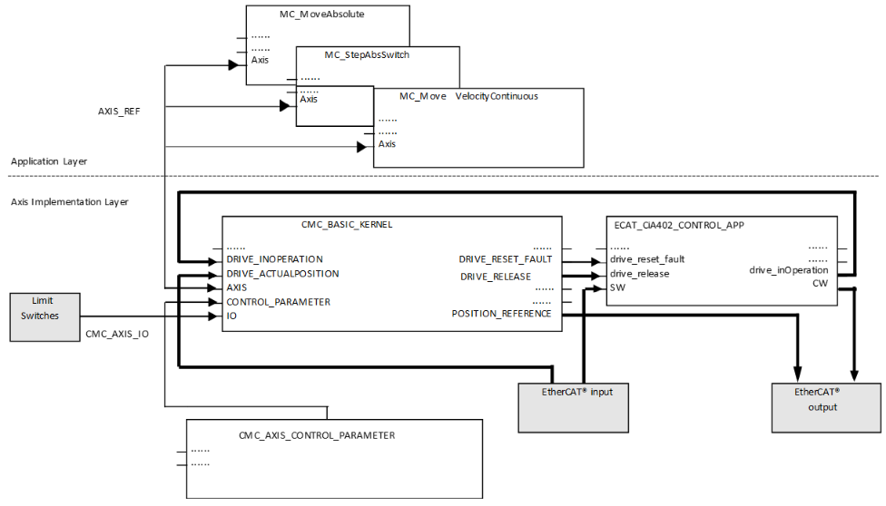
In the example the main signals are to be transferred via EtherCAT network. The drive control function block for the Microflex e190 can be found in the ABB_Ecat_CiA402_AC500.library.
If using the AC500-eCo PLCs, use the OBIO_PTOMotionKernel function block (separate library ABB_MotionControlEco_AC500.library) instead of CMC_Basic_Kernel for the PTO functionality.
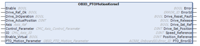
In the eCo PLC, if PWM is used in the configuration, use the kernel function block OBIO_PWMMotionKernel function block instead of CMC_Basic_Kernel function block.