


Create a project with the following program PLC_PRG:
PROGRAM PLC_PRG
VAR
	iVar : INT;
	rSin : REAL;
	rVar : REAL;
END_VAR

iVar := iVar + 1;
iVar := iVar MOD 33;

rVar := rVar + 0.1;
rSin := 30 * SIN(rVar);
-
In the device tree, select the application and add a new visualization by clicking “Project Add Object Visualization”.
The respective visualization editor opens.
-
Add the “Visualization” object to the device tree below “Application”.
An empty visualization appears.
-
Open “Toolbox Special Controls”.
-
Drag the “Trace” element to the visualization editor.
The element properties are displayed on the right side.
-
Click the symbol
 in the “Trace” property.
The “Trace Configuration” dialog opens.
-
Click “Add Variable” to add an entry to the tree view of the trace configuration and select a project variable (for example,
PLC_PRG.rSin). -
Click the top node of the trace configuration.
The group “Record Settings” is shown on the right.
-
Select the
MainTaskoption for the “Task” setting.Tip: The trace recording and the corresponding program should be executed in the same task.
-
Click “OK”.
The task configuration is applied.
-
Select the trace element and click “Visualization Add Elements for Trace Control”
The “Trace Wizard” dialog opens. By default, all control elements are activated there.
-
Click “OK” to close the dialog.
The control elements are added to the visualization and the control variables are declared. Then the control elements and the trace element are configured with the control variables.
-
Download the application to the controller and start it.
Example
Record the sine-shaped data of the IEC variable PLC_PRG.rSin
The PLC_PRG program is running on the PLC. When you follow the "Getting Started" instructions,
the following interface is displayed:
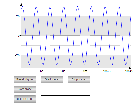
You can control the trace recording by clicking the buttons.