


The ABB_MotionControlLoad_AC500 library is an extension to ABB_MotionControl_AC500 library based on PLCopen part 6 called “fluid power” and basically can be used to implement load control as a simple form of torque profiling. It can be used together with all other motion control package libraries. The same structure and general rules are applied and all the above chapters in this document is relevant for ABB_MotionControlLoad_AC500 library as well. It is recommended to read through all the above chapters before start using the function blocks from this library. A difference is that the position control loop has to be closed inside the PLC as it is to be synchronized with the load control loop which is also realized. The implementation of Load function blocks is based on the PLCopen part 6 – Fluid power.
Overview of the defined extended function blocks:
|
Administrative |
Motion |
||
|---|---|---|---|
|
Single axis |
Multiple axis |
Single axis |
Multiple axis |
|
MC_LimitLoad |
- |
MC_LoadControl |
- |
|
MC_LimitMotion |
- |
MC_LoadSuperImposed |
- |
|
- |
- |
MC_LoadProfile |
- |
|
- |
- |
MC_TorqueControl |
- |
As per PLCopen MC_TorqueControl is a part 1 function block, however due to its implementation as a wrapper for the load control and limit load blocks this is added to ABB_MotionControlLoad_AC500 library.
The following state diagram is based on the version as defined in ‘Part 1 – Function Blocks for Motion Control’, Version 2.0.
This specification adds three load function blocks to the state diagram:
-
MC_LoadControl
-
MC_LoadSuperImposed
-
MC_LoadProfile
MC_TorqueControl function block also follows the same state diagram.
Function blocks not listed in the state diagram do not affect the state diagram, meaning that whenever they are called the state does not change.
The state diagram shows synchronized motion because the position-axis follows the load, and the state is related to the position axis.
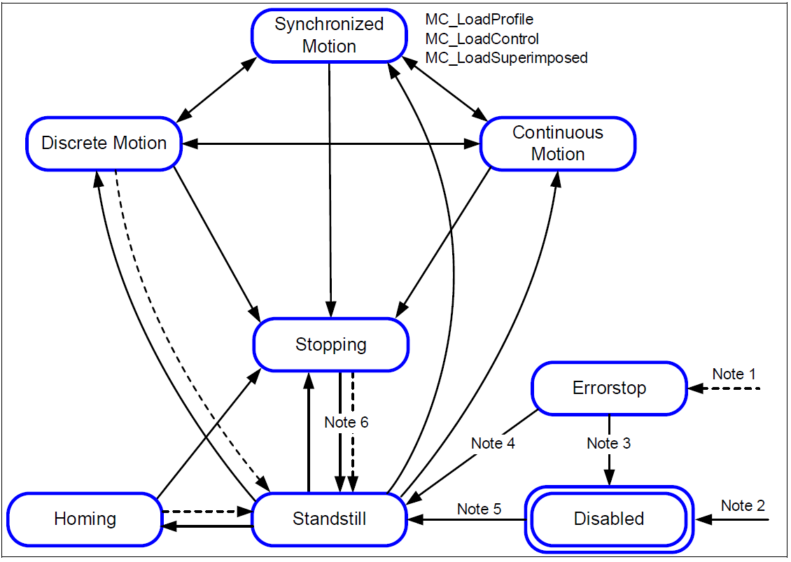
- Note 1:
-
From any state. An error in the axis occurred.
- Note 2:
-
From any state. MC_Power.Enable = FALSE and there is no error in the axis
- Note 3:
-
MC_Reset and MC_Power.Status = FALSE
- Note 4:
-
MC_Reset and MC_Power.Status = TRUE and MC_Power.Enable = TRUE
- Note 5:
-
MC_Power.Enable = TRUE and MC_Power.Status = TRUE
- Note 6:
-
MC_Stop.Done = TRUE and MC_Stop.Execute = FALSE
Kernel function block - Fluid power
The basic block is the CMC_Load_Motion_Kernel. It has to be called every cycle and at least once before any MC… block is activated. It is used to combine the position and velocity functionality from CMC_Basic_Kernel with the load control functionality which is utilized by the MC_Load... blocks.

The reference which is used by the CMC_Load_Motion_Kernel is equivalent with the Speed_Reference at CMC_Basic_Kernel, as long as no LOAD-functionality is activated. The documentation from CMC_Basic_Kernel applies to the identical inputs and outputs. Some inputs and outputs are added to serve the load control functionality.
The Load_Ref is used instead of Axis_Ref for the MC_Loadxxx blocks. When the CMC_Load_Motion_Kernel is used, Load_Ref replaces Axis_Ref and user can use all PLCopen-Blocks.
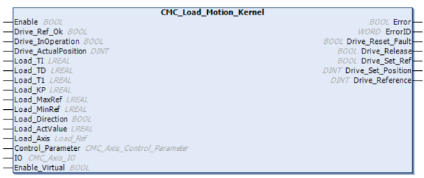
The actuator (drive) has to be accessed outside the CMC_Load_Motion_Kernel block. Actual values and reference values might be transferred by a synchronised bus or by I/Os.
-
•All inputs and outputs of the function block which are named “DRIVE_xxxx” should be used to connect to the actuator (drive). It does not matter whether this connection is done by fieldbus or by conventional IOs.
The Axis-structure is used to connect to the PLCopen blocks
-
The Load_Axis structure is used to connect the fluid-power PLCopen blocks
-
The control_parameter-structure is used for configuration of control loop.
-
The IO-structure gives a connection to limit- or reference switches.
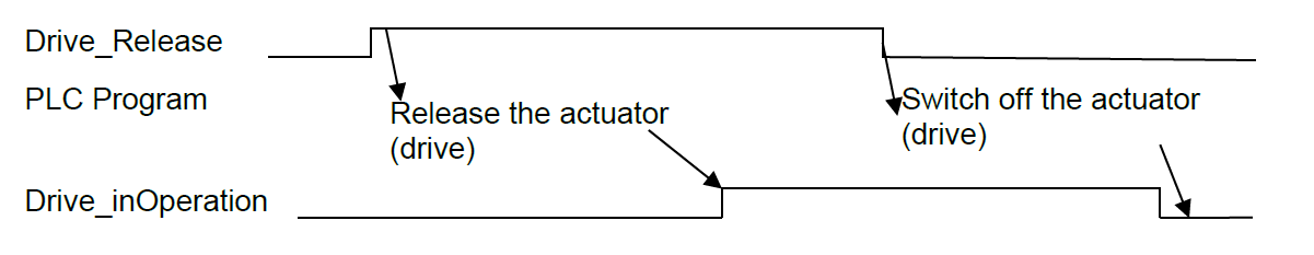
When the function block will take control (close loop) the output “Drive_Release“ is set. The PLC-Program should then start the actuator (actuator (drive)) and set “Drive_InOperation = TRUE” when successful. In case of actuator (actuator (drive)) problem, “Drive_InOperation” should be reset. The function block will then open the position control loop and Speed_Reference will be 0.
The homing is done with PLCopen-blocks. As the interface to the actual position is outside the CompactMotion, the bit “Drive_Set_Ref” is set when the state is reached to evaluate the zero-track. When the zero-track was found, Drive_ActualPosition has to be set to “Drive_Set_Position”, this has to be indicated by “Drive_Ref_Ok”.
The output “Drive Reference” should be send to the actuator (drive). This value is scaled with Max_Rpm and Max_Reference which means: when “Drive_Reference” equals Max_Reference, the motor is expected to run with Max_Rpm.
Load control
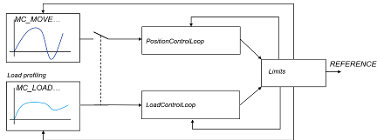
The function block holds a position control loop and a load control loop. The load control loop is a PIDT1-Block. Both control loops are alternately activated, depending if a MC_Load..block or a MC_Move… block is active. There is a bumbless transition realized between the different control loops.
The PIDT1 controller has a proportional, integral and derivative part. The integral and derivative part can be switched of by using a time value = 0.
Transfer function
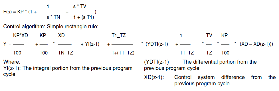
All 3 parts of the control loop are added up. The integral or derivative part could be disabled by setting the respective time constant to 0, so the following structures are possible:
-
P
-
PDT1
-
PI
-
PIDT1
The Load_MaxRef and Load_MinRef values will limit the controllers output Y and also apply to the controller’s internal integral part. I.e the integral part can only hold values between the high and low limits. If the manipulated variable Y reaches one of the two limits, the controller's integral part is no longer changed. This prevents the integral part from holding meaningless values and, in certain circumstances, not returning to the operating range for a long time. This behavior of a controller is also referred to as a "special anti-reset windup measure".
Example - Fluid power extensions
MC LimitLoad
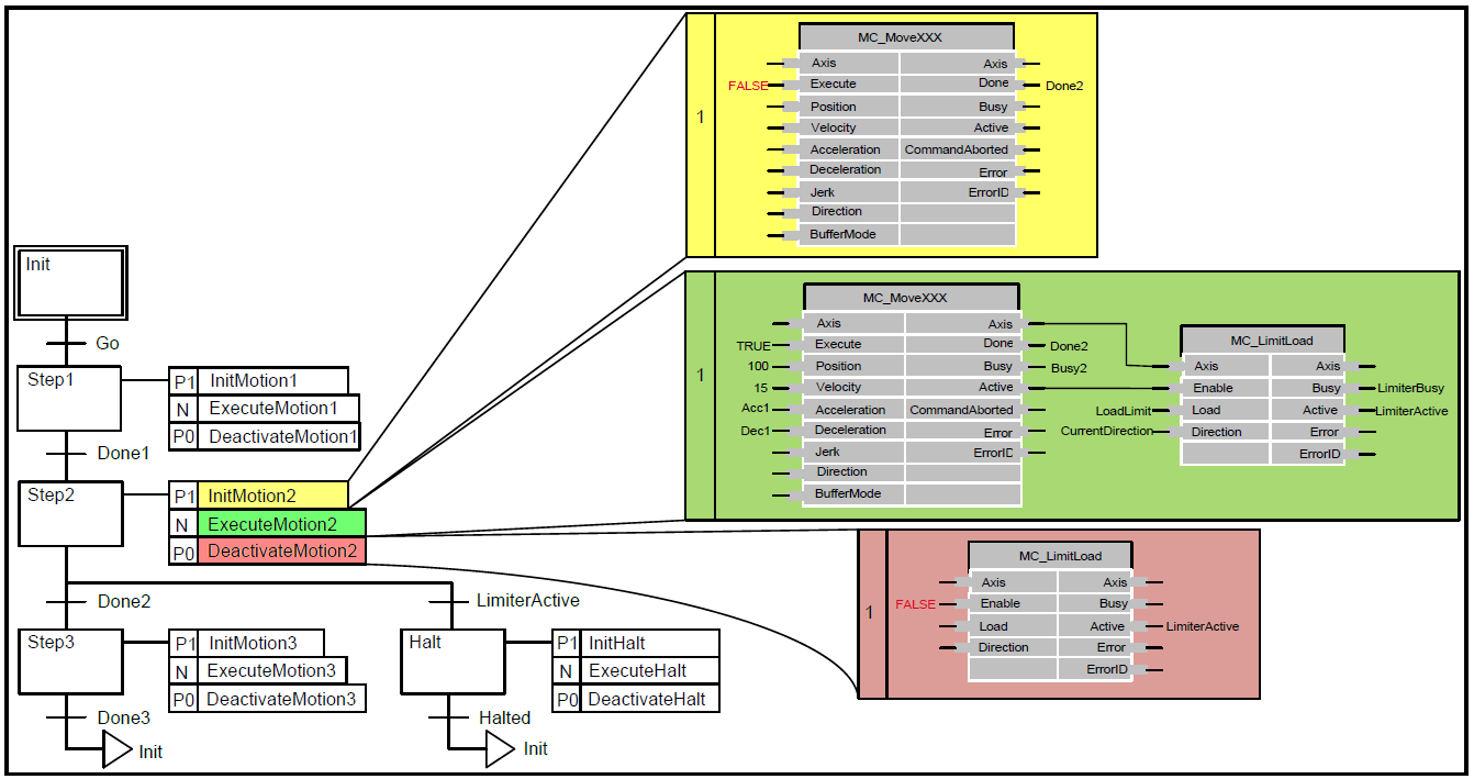
In the diagram below, an example is explained. SFC is used here to distinguish between a movement where the MC_LimitLoad functionality has become ‘Active’ or not. In Step 2 there is a movement like ‘MoveAbsolute’, which is limited by the MC_LimitLoad functionality. If the absolute position is reached without MC_LimitLoad becoming active, the transition via done to step 3 is applicable. However, if the MC_LimitLoad becomes ‘Active’, the transition to the ‘Halt’ step is applicable, issuing a MC_Halt.
MC_LimitMotion e.g. force fitting
The function block is intended to be used in conjunction with a MC_LoadControl or MC_TorqueControl having primary control on the axis. The MC_LimitMotion should be enabled by the ‘Active’ output of the MC_LoadControl / MC_TorqueControl. If motion values on the axis exceed the given limit, appropriate measures are taken to keep to these limits, implying that the load/torque will not follow the programmed trajectory but depend on the external load conditions. However, the ‘Active’ output of the MC_LoadControl/MC_TorqueControl will stay TRUE in this case, following the modified PLCopen definition “The ‘Active’ output indicates, that the FB has control on the set-value generation of the axis”. This is despite the fact, that physically only the load-conditions or the movement of an axis can be controlled. With actual motion states below programmed limits, the programmed load/torque trajectory will proceed. Enabling the limiter block with activation of the MC_LoadControl/MC_TorqueControl ensures that limits are only supervised when the MC_LoadControl/MC_TorqueControl takes control on the axis for the first time. Disabling the limiter block with de-activation of the MC_LoadControl/MC_TorqueControl ensures that limits are no more supervised when the MC_LoadControl/MC_TorqueControl loses control on the axis by ‘CommandAborted’ or ‘Error’.
MC_ LoadSuperImposed
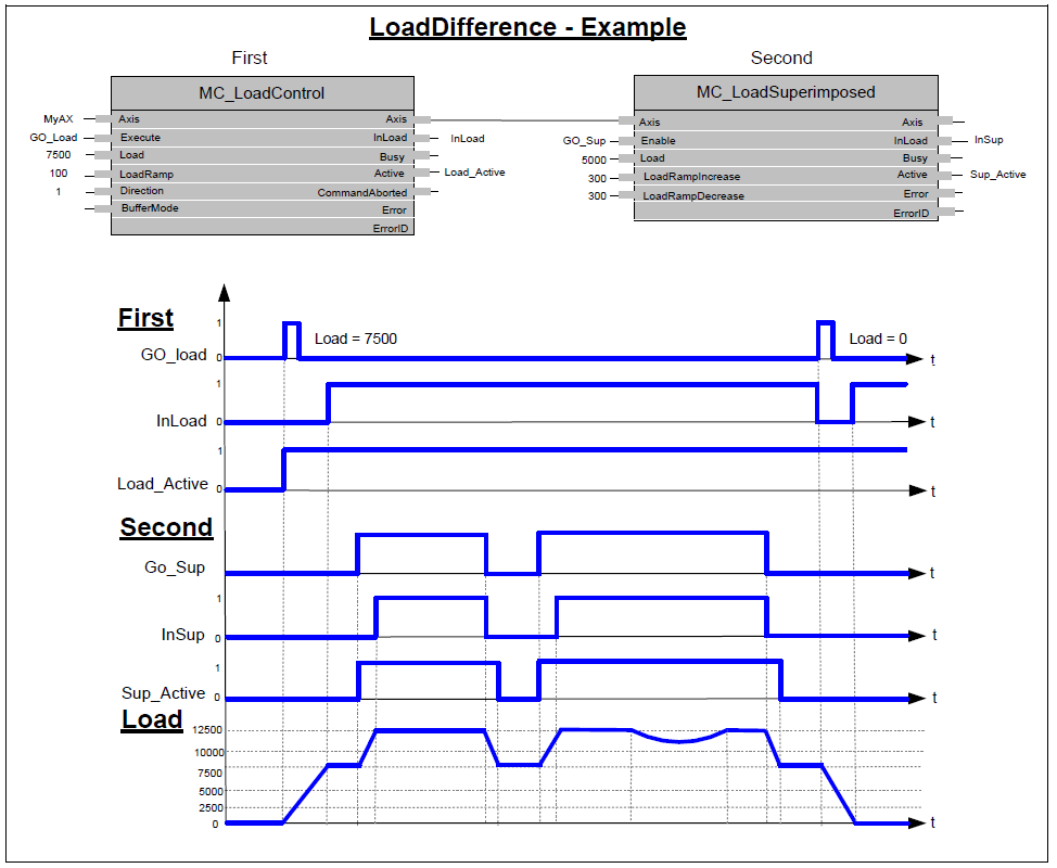
Possible Application: Actuator: hydraulic cylinder with fluid pressure sensor actuates the press of plastic injection molding machine in a continuous load operation.
Request: Prior to MC_LoadSuperImposed call, a MC_LoadControl block is ‘Active’ with a command of 7,500 kPa to press melted plastic into the mold. Once the MC_LoadControl ‘InLoad’ condition is achieved a superimposed pressure of 5,000 kPa is added several times to cause a hammering effect to relieve stresses in the plastic.
Result: the MC_LoadControl pressure command of 7,500 kPa is superimposed with a discrete pressure command of 5,000 kPa. Once the ‘LoadSuperImposed’ command is active the system pressure rises to 12,500 kPa.
When the superimposed pressure command has been achieved the MC_LoadSuperImposed block is done and the original command given by the MC_LoadControl resumes the original pressure command. The MC_LoadSuperImposed block is executed several times without affecting the original pressure command given by the MC_LoadControl block.
MC_TorqueControl
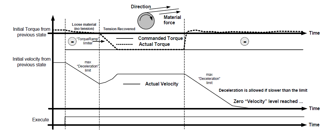
The example (below) opposite signs for ‘Direction’ & ‘Torque’ are used (e. g. Retention or brake control). (In the function block: +Direction –Torque). It is like an unwinding application with torque on the material, and a break in the material. When the material breaks, as shown in the middle of the figure this causes a drop in the real Torque value (in absolute terms): The velocity will decrease, limited by the fastest “deceleration” limit specified by the ‘Deceleration’ VAR_INPUT down to zero velocity (with no tension there is a risk of having shock breakings, so we have to limit to the fastest). In this case the torque setpoint might not be achieved.
In an unwinding application (derived from this brake control) material tension is the target, not motor torque. The instantaneous diameter of the roll should be taken into account to transform the “User tension setpoint”. Also, additional inertia compensation by modification of the torque setpoint for acceleration / deceleration is common from instantaneous weight data (weight is commonly estimated from diameter). Additionally, in unwinding applications, in the case of loose material (same condition as material break), a negative slow velocity reference is usually applied to “rewind” the loose material. In this case, this must be provided by external programming.