

Configuration is valid as of CPU firmware 3.5.0 (“CM589-PNIO”) respectively CPU firmware 3.6.0 (“CM589-PNIO-4”) and “CM589-PNIO” FW 1.6.2.20.
The configuration of the “CM589-PNIO” PROFINET I/O module has to be done in the following steps:
-
Parameterization of the AC500 communication module interface ⮫ “Parameterization - communication module interface”
-
Parameterization of the PROFINET IO device protocol stack ⮫ “Parameterization - PROFINET I/O stack”
-
Configuring PROFINET IO device module structure ⮫ “Configuring PROFINET IO structure”
-
Parameterization of the PROFINET IO device modules ⮫ “Parameterization - PROFINET IO device modules”
-
Mapping of the I/Os ⮫ “Mapping of the I/Os”
-
Configuration specific to CM589-PNIO-4 ⮫ “Configuration CM589-PNIO-4”
Configuration procedure for “CM589-PNIO” and “CM589-PNIO-4” are basically the same. Thus this description refers to “CM589-PNIO” only. Differences between “CM589-PNIO” and “CM589-PNIO-4” will be highlighted explicitly if necessary!
Parameterization - communication module interface
For connecting a PLC as “PROFINET-IO-Device”, plug “CM589-PNIO” / “CM589-PNIO-4” at the “Extension_Bus” node.
Double-click on “CM589-PNIO” to open the “CM589-PNIO” configuration in the editor window.
|
Parameter |
Value |
Default Value |
Description |
|---|---|---|---|
|
Run on config fault |
No |
No |
In case of a configuration error, the user program is not started. |
|
Yes |
The user program is started even in case of configuration error. |
||
|
Bus state in Stop |
Operation |
Defines the behavior of the fieldbus when the PLC is in Stop. In “PLC Settings” IO update and behavior of outputs in stop can be configured. |
|
|
Stop |
The protocol of the fieldbus is stopped. There is no communication between PROFINET controller and devices. |
||
|
Operation |
The protocol of the fieldbus is executed. The communication between PROFINET controller and devices is enabled. |
Click on tab “CM589-PNIO I/O Mapping” to get “Bus Cycle Options” in the editor window.
|
Parameter |
Value |
Default Value |
Description |
|---|---|---|---|
|
Bus cycle task |
Use parent bus cycle settings |
Use parent bus cycle settings |
Settings from “PLC settings” tab are used. |
|
Task |
Name of task that triggers the bus cycle. |
Click on tab “CM589-PNIO IEC Objects”. Here the IO driver instance of communication module is specified.
Parameterization - PROFINET I/O stack
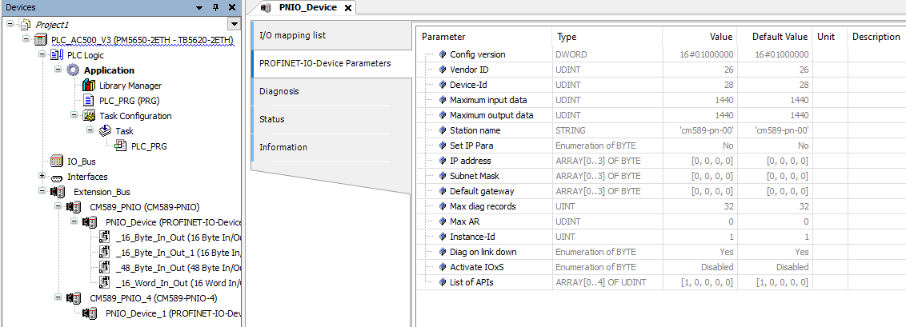
All parameters for “PROFINET-IO-Device” protocol configuration are set automatically by Automation Builder. These parameters are displayed just for information and in read-only mode. Double-click on “PROFINET-IO-Device” in tree view will show the parameter set in tab “PROFINET-IO-Device Parameters”.
-
“Station name”: The default name is displayed. The real name used on acting at the field bus is combined out of this default name and the used setting of the rotary switches at the CM589 module (“cm589-pnio-00”, “00” will be replaced by rotary switch value) or the name set via PROFINET set name service.
-
Parameter “IP address”, “Subnet Mask”, “Default gateway”: The default values are displayed here. These values are not used as communication settings. PROFINET IO controller supplies the IO devices with IP settings on communication establishing.
Configuring PROFINET IO structure
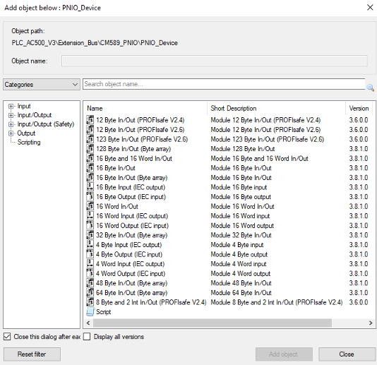
“CM589-PNIO” provides I/O data as modules with different data types and directions. Create an application specific I/O structure by compiling an appropriate combination of modules.
To assign I/O modules to “PROFINET-IO-Device” node open “Add object” dialog.
The maximum image size available for I/O data depends on “CM589-PNIO” modules firmware revision. If firmware revision run by connected “CM589-PNIO” module does not support the number of I/O data configured, download configuration will fail. Currently see ⮫ “Calculating size of I/O data” how to calculate number of I/O data occupied by certain configuration.
There are new I/O modules, introduced for V3 PLCs, defined as "ARRAY OF BYTE":
-
16 Bytes Input/Output
-
32 Bytes Input/Output
-
48 Bytes Input/Output
-
64 Bytes Input/Output
-
128 Bytes Input/Output
PROFIsafe modules can only be used if a SM560-S-FD1 (for “CM589-PNIO”) respectively SM560-S-FD4 (for “CM589-PNIO-4”) was configured in project. For details see safety documentation.
Parameterization - PROFINET IO device modules
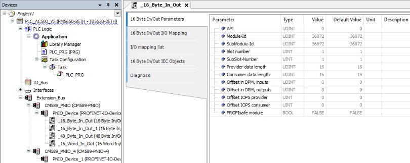
PROFINET IO device modules do not need user configuration. All needed parameters are set automatically by Automation Builder. Double-click on a module node shows the parameter set just for information. This parameter set is identical for all module types and is displayed in read-only mode.
-
“API”: Shows the API which is used by the “CM589-PNIO” modules. As API 0 is supported only “CM589-PNIO” modules do not provide configuration capabilities for this parameter.
-
“Slot number”, “SubSlot-Number”, “Offset in DPM”, inputs/outputs: Will be set to default values on inserting a module. On creating configuration data Automation Builder calculates real values and overwrites the defaults.
-
“Offset IOPS” provider/consumer: Not used and set to 0 values.
-
“PROFIsafe module”: “FALSE” if module is not a safety module.
Calculating size of I/O data
PROFINET defines I/O data and status information to be exchanged between IO controller and IO device. The status information is called “Provider Status” and “Consumer Status”. Both (I/O data and status information) have to be considered on calculating allocated memory in input and output image.
-
The number of status bytes depends on the type of module used.
-
The different types of modules input, output and in/output have to be considered different.
-
Some status bytes are reserved for predefined submodules have to be considered additionally.
A configured I/O module allocates memory space at the corresponding I/O image for data and status bytes. Additionally memory is allocated at the opposite directions I/O image to store further status bytes. E.g. an input module allocates memory at the input image but additionally it allocates one byte for status at the output image. Summarized size of input and output data and status has to fit to the corresponding image.
|
Module type |
Input data |
Output data |
||||
|---|---|---|---|---|---|---|
|
Inputs |
Provider status inputs |
Consumer status outputs |
Outputs |
Provider status outputs |
Consumer status inputs |
|
|
Reserved |
0 input bytes |
4 bytes |
0 bytes |
0 bytes |
0 bytes |
4 bytes |
|
Input module (e.g. 4 byte input) |
n input bytes |
1 byte |
0 bytes |
0 bytes |
0 bytes |
1 byte |
|
Output module |
0 input bytes |
0 bytes |
1 byte |
n output bytes |
1 byte |
0 bytes |
|
Input/output module |
n input bytes |
1 byte |
1 byte |
n output bytes |
1 byte |
1 byte |
Following expressions calculate allocated sizes of input and output data:
|
Size input = |
Input + status + 4 bytes (reserved status) |
|
Size output = |
Output + status + 4 bytes (reserved status) |
-
Input = Summarized number input bytes all modules.
-
Output = Summarized number output bytes all modules.
-
Status = Count input modules + count output modules + 2 * count input/output modules.
Mapping of the I/Os
Double-click on the desired “PROFINET-IO-Device” module object in the device tree to show current I/O mappings connected to this module.
Symbolic names for variables, inputs and outputs for further details on mapping inputs and outputs.
Configuration CM589-PNIO-4
“CM589-PNIO-4” adds PROFINET “Shared Device” feature to already described “CM589-PNIO” device functionality. Thus “CM589-PNIO-4” is able to communicate to 4 different PROFINET IO controllers in parallel.
Shared device usage of a “CM589-PNIO-4” does not need to be considered on doing the configuration of the “CM589-PNIO-4” coupler device itself. It has to be considered only on doing the configuration of “CM589-PNIO-4” as child to the “CM579-PNIO” IO controller. See “CM579-PNIO” configuration for details.
Diagnosis and debugging
“CM589-PNIO” – PROFINET device diagnosis
The diagnosis messages of communication module “CM589-PNIO” are displayed in tab “Diagnosis” of node “CM589-PNIO” in device tree of Automation Builder. Within PLC application they can be read with the diagnosis methods of IO driver or function block “Diag”.
⮫ “Method Ack / DiagAck: acknowledgement”
In PLC display the diagnosis messages of “CM589-PNIO” are not shown.