

For a detailed description of the mounting, disassembly and connection of the module, please refer to the ⮫ installation instructions.
The connection is carried out by using removable 9-pin and 11-pin terminal blocks. These terminal blocks differ in their connection system (spring terminals or screw terminals, cable mounting from the front or from the side). The terminal blocks are not included in the module's scope of delivery and must be ordered separately.
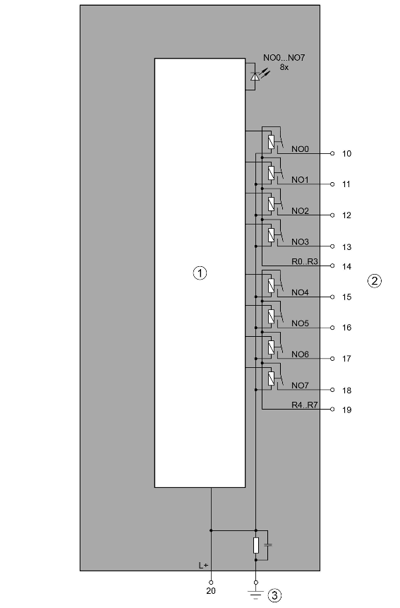
1
Logic - I/O interface
2
Digital outputs
3
Functional earth connection
|
Terminal |
Signal |
Description |
|---|---|---|
|
10 |
NO0 |
Normally-open contact of the output NO0 |
|
11 |
NO1 |
Normally-open contact of the output NO1 |
|
12 |
NO2 |
Normally-open contact of the output NO2 |
|
13 |
NO3 |
Normally-open contact of the output NO3 |
|
14 |
R0..3 |
Output common for signals NO0 to NO3 |
|
15 |
NO4 |
Normally-open contact of the output NO4 |
|
16 |
NO5 |
Normally-open contact of the output NO5 |
|
17 |
NO6 |
Normally-open contact of the output NO6 |
|
18 |
NO7 |
Normally-open contact of the output NO7 |
|
19 |
R4..7 |
Output common for signals NO4 to NO7 |
|
20 |
L+ |
Process voltage L+ +24 V DC |
The internal power supply voltage for the module's circuitry is carried out via the I/O bus (provided by a communication interface module or a CPU). Thus, the current consumption from 24 V DC power supply at the terminals L+/UP and M/ZP of the CPU/communication interface module increases by 5 mA per DO571.
The external power supply connection is carried out via the L+ (+24 V DC) terminal. The negative pole of the external power supply is realized via the I/O bus. Therefore, the CPU/communication interface module and the DO571 must have a common power supply.

WARNING
Risk of death by electric shock!
Hazardous voltages can be present at the terminals of the module.
Make sure that all voltage sources (supply voltage and process supply voltage) are switched off before you begin with operations on the system.
For screw-type terminals only:
WARNING
For screw terminals only: Danger of death by electric shock!
The IP 20 protection degree is only provided if all terminal screws are tightened.
Tighten all screws of unused load terminals of relay outputs if voltages > 24 V are connected to the relay group.
WARNING
Removal/Insertion under power
The devices are not designed for removal or insertion under power. Because of unforeseeable consequences, it is not allowed to plug or unplug devices with the power being ON.
Make sure that all voltage sources (supply and process voltage) are switched off before doing the following:
-
Connect or disconnect any signal or terminal block.
-
Remove, mount or replace a module.
Disconnecting any powered devices while energized in a hazardous location could result in an electric arc, which could create a flammable ignition resulting in fire or explosion.
Make sure that power is removed and that the area has been thoroughly checked to ensure that flammable materials are not present prior to proceeding.
The devices must not be opened when in operation. The same applies to the network interfaces.

NOTICE
Risk of damaging the PLC modules!
Overvoltages and short circuits might damage the PLC modules.
-
Make sure that all voltage sources (supply voltage and process supply voltage) are switched off before you begin with operations on the system.
-
Never connect any voltages or signals to reserved terminals (marked with ---). Reserved terminals may carry internal voltages.
NOTICE
Risk of damaging the PLC module!
The PLC module can be damaged by overload.
Make sure that the total current of each output common terminal (R0 ... R3 and R4 ... R7) does not exceed 8 A.
Never connect total currents > 8 A per group.
If the group fuse protection is not sufficient, then individual fuse protection of the outputs should be used.
Connection of the module:
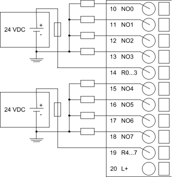
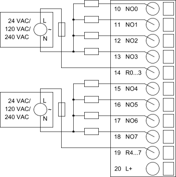
NOTICE
Risk of damaging the I/O module!
The outputs are not protected against short circuit and overload.
-
Never short-circuit or overload the outputs.
-
Never connect inductive loads without an external suppression against voltage peaks due to inductive kickback.
-
Never connect voltages > 240 V. All outputs must be supplied from the same phase.
-
Use an external 5 A fast protection fuse for the outputs.
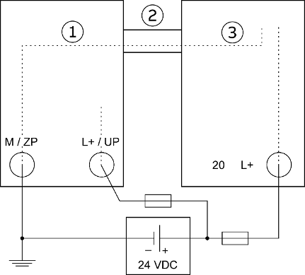
1
CPU or communication interface module
2
I/O bus
3
DO571
The L+ connection of the DO571 and the 24 V supply of the CPU/communication interface module must be connected to the same 24 V power supply.
The module provides several diagnosis functions⮫ “Diagnosis”.
The meaning of the LEDs is described in the section Status LEDs⮫ “State LEDs”.