


Example
In the example, the PLC consists of the following devices:
-
AC500 processor module with Ethernet interface.
-
4 communication modules.
-
7 I/O modules (digital and analog).
-
The compatible terminal bases and terminal units.
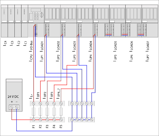
Because of the high total current consumption of the digital I/O modules (from UP = 24 V DC), the supply is divided up into several electric circuits fused separately.
The maximum permitted total current over the supply terminals of the I/O terminal units is 8 A.
The total current can be calculated as follows:
ITotal = IL+ + IUP
with the assumptions
IL+ = ICPU + II/O bus + IC1 + IC2 + IC3 + IC4 (CPU + communication modules + I/O bus)
II/O bus = Number of expansion modules × Current consumption through the I/O bus per module
and
IUP = IUP1 + ILOAD1 + IUP2 + ILOAD2 + IUP3 + ILOAD3 + IUP4 + ILOAD4 + IUP5 + ILOAD5 + IUP6 + ILOAD6 + IUP7 + ILOAD7
If one assumes that all outputs are switched on and are operated with their maximum permitted load currents (under compliance with the maximum permitted currents at the supply terminals), then the following values are the result for an example shown above:
|
|
ICPU *) |
ICx *) |
II/O bus *) |
IUPx *) |
ILOADx *) |
|---|---|---|---|---|---|
|
CPU/communication module part |
|||||
|
CPU |
0.110 A |
- |
- |
- |
- |
|
C1 |
- |
0.050 A |
- |
- |
- |
|
C2 |
- |
0.085 A |
- |
- |
- |
|
C3 |
- |
0.050 A |
- |
- |
- |
|
C4 |
- |
0.050 A |
- |
- |
- |
|
I/O module part |
|||||
|
Analog1 |
- |
- |
0.002 A |
0.150 A |
- |
|
Analog2 |
- |
- |
0.002 A |
0.150 A |
0.160 A |
|
Analog3 |
- |
- |
0.002 A |
0.100 A |
0.080 A |
|
Analog4 |
- |
- |
0.002 A |
0.100 A |
0.080 A |
|
Digital1 |
- |
- |
0.002 A |
0.050 A |
8.000 A |
|
Digital2 |
- |
- |
0.002 A |
0.050 A |
8.000 A |
|
Digital3 |
- |
- |
0.002 A |
0.050 A |
8.000 A |
|
S columns |
0.110 A |
0.235 A |
0.014 A |
0.650 A |
24.320 A |
|
S IL+ ≈ 0.4 A |
S IUP ≈ 25 A |
||||
|
ITotal ≈ 25.4 A |
|||||
|
*) All values in this column are exemplary values |
|||||