


Configuration and programming
Configuration and programming of all AC500 control systems (processor modules) is done by using Automation Builder software.
Features:
-
Standardized programming according to IEC 61131-3, five programming languages (Structured Text (ST), Function Block Diagram (FBD), Instruction List (IL), Ladder Diagram (LD), Sequential Function Chart (SFC)), Continuous Function Chart (CFC), debugging functions for program test
-
Online diagnosis
-
Debugging functions for the program test: Single step, single cycle, breakpoint
-
Offline simulation - simulate commands without PLC being connected
-
Sampling trace - timing diagrams for process variables
-
Recipe management and watch lists
-
Visualization
-
Configuration of the communication interface modules (for PROFINET, PROFIBUS, EtherCAT, CANopen, Ethernet, Modbus)
-
Programming - serial or via Ethernet networks
-
Comprehensive libraries
-
Export and import interfaces for devices, signals, applications, visualization, etc.
-
Multi-user support and project compare
-
Project scripting
Offline simulation
IEC 61131-3 commands can be simulated without a PLC being connected, including the relevant malfunctions. After the program test, the application can be downloaded to the control system.
Sampling trace
Timing diagrams for process variables and storage of data in a circular buffer with event trigger.
Recipe management and watch lists
Values of selected variables are displayed. Pre-defined values can be assigned to variables which can then be downloaded to the control system all at once ("Write recipe" ). Actual values from the control system can also be pre-assigned for reading into the Watch and Recipe Manager, and stored in memory there ("Read recipe"). These functions are also helpful, for example, for setting and entering control parameters.
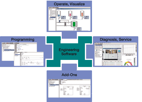
Visualization
Includes color change, moving elements, bitmaps, text display, allows input of setpoint values and display of process variables read from the PLC, dynamic bar diagrams, alarm and event management, function keys and ActiveX elements.
Programming
The Ethernet interface of the processor modules is used to connect to the engineering software for programming, debugging and diagnosis.
Engineering interface
Provides access from the programming system to an external project database in which the program source code of one or several automation projects is managed. Optionally, a version control system can be used in order to ensure data consistency of the program code for several different users and projects.