


The synchronized I/O bus is the I/O data bus for the I/O modules connected with the processor modules or communication interface modules. Through this bus, I/O and diagnosis data are transferred.
With its fast data transmission, the I/O bus obtains very low reaction times.
Up to 10 I/O terminal units (for one I/O module each) can be added to one terminal base or to one AC500-eCo processor module. The I/O terminal units and the AC500-eCo I/O modules, have a bus input at the left side and a bus output at the right side. Thus the length of the I/O bus increases with the number of attached I/O modules⮫ Table 146 “Maximum number of I/O devices which can be connected to the I/O bus”.
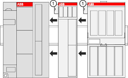
1
I/O bus connection
The connection of the I/O bus is performed automatically by telescoping the modules on the DIN rail.
The I/O bus provides the following signals:
-
Supply voltage of 3.3 V DC for feeding the electronic interface components.
-
3 data lines for the synchronized serial data exchange.
-
Several control signals.

NOTICE
Except when using hot-swap terminal units, the I/O bus is not designed for inserting and removing modules during operation.
If a module is inserted or removed on a terminal unit that is not hot-swap capable while the bus is running, the following consequences are possible:
-
Reset of the station or of the processor module.
-
System lockup.
-
Damage of the module.

WARNING
Removal/Insertion under power
Removal or insertion under power is permissible only if all conditions for hot swapping are fullfilled.
⮫ “Replace an I/O module with hot swap”
The devices are not designed for removal or insertion under power when the conditions for hot swap do not apply. Because of unforeseeable consequences, it is not allowed to plug in or unplug devices with the power being ON.
Make sure that all voltage sources (supply and process voltage) are switched off before doing any of the following actions:
-
Connect or disconnect any signal or terminal block.
-
Remove, mount or replace a module.
Disconnecting any powered devices while they are energized in a hazardous location could result in an electric arc, which could create an ignition source resulting in fire or explosion.
Prior to proceeding, make sure that power is disconnected and that the area has been thoroughly checked to ensure that flammable materials or ignitable concentrations are not present.
The devices must not be opened when in operation. The same applies to the network interfaces.
Profibus (master and slave) and CM589-PNIO are available since version 2.5.0 of the Automation Builder.