


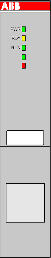
Processor modules
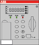
AC500 processor modules contain the CPU with the core component of the PLC. The CPU is connected with the user memory, input and output module, communication port and other units via the system bus and performs tasks by means of system programs preset in the system memory. The CPU adopts the function preset by the application program to command the PLC for operation.
The CPU has the following functions:
-
To receive user programs and data entered
-
To diagnose work faults of the power supply and PLC circuit as well as syntax errors in programming
-
To receive the state or data of the site via the input interface and save it into the shadow register or data register
-
To read the user programs in the memory one by one and execute them after interpretation
-
To updating the state of the associated flag bits and the contents of the shadow register according to the execution results and providing output control using the output unit.
Processor modules are available in different performance classes. Only one processor module is required for a valid system architecture.
There are different types of processor module available that differ in the features and functions they provide, e.g. performance, LED display etc.
If required, processor modules are also available with an integrated Ethernet communication module (TCP/IP).
Communication modules
AC500 communication modules are required for the following:
-
The connection to standard fieldbus systems.
-
The integration into existing networks.
-
The communication modules enable communication on different fieldbuses.
-
The communication modules are mounted on the left side of the processor module on the same terminal base.
-
The communication modules are directly powered via the internal communication module bus of the terminal base.
A separate voltage source is not required.
Terminal bases
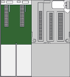
The terminal base is needed for mounting and connecting the processor module and the communication modules. The modules are plugged on the terminal base.
The AC500-eCo processor modules and special AC500 (e.g. PM595) processor modules don't have a removable terminal base. The connections normally supported by a terminal base are part of the device.
I/O modules
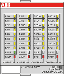
The I/O modules are the input/output unit which connects the PLC with the process. The PLC can detect controlled object data via the input interface and the data is taken as the basis for PLC control on the controlled object. In addition, the PLC sends processing results via the output interface to the controlled object to execute the control.
External input equipment and output equipment needs various signal levels whereas the information processed by the processor module in the PLC can only be the standard level. In order to perform this conversion, the I/O interface generally uses optical isolation and filtering to improve the interference immunity of the PLC. In addition, the I/O interface can generally indicate the working state to facilitate maintenance.
The PLC provides multiple I/O interfaces for operation level and drive capability to users for selection such as digital input, digital output, analog input, analog output, etc. I/O interfaces of the PLC interpret the number of input/output signals as the number of PLC I/O points. The number of I/O points is an important basis for PLC selection. If the system has insufficient I/O points, it can be expanded via the I/O extension interface of the PLC.
The I/O modules for digital and/or analog inputs and outputs are available in different versions and allow flexible use thanks to configurable channels.
The modules can be simply plugged onto a terminal unit for a centralized or decentralized I/O extension via communication interface modules.
Terminal units
I/O modules and function modules are plugged on a terminal unit.
Terminal units enable simple prewiring without electronics and are available for 24 V DC and 120/230 V AC, optionally for spring or screw-type terminals.
Communication interface modules
Communication interface modules are used to build decentralized I/O stations in decentralized systems. They contain the fieldbus interface and a set of onboard I/O channels. Additional I/O modules can be attached to build larger decentralized I/O stations. A communication interface module is mounted on a terminal unit.
Function modules
Function modules extend the PLC system to perform special task control. These modules often provide independent components such as a CPU, system programs, memory and interfaces connected with the PLC system bus.
Function modules are connected with the PLC via the I/O bus to exchange data and independently work under cooperative management of the PLC.
Memory
In the PLC, the memory is mainly used for saving system programs, user programs and work data. There are two types of memory: volatile memory and non-volatile memory.
-
Volatile memory:
All saved data will be lost after power failure of the memory but the memory can provide a high access rate and unlimited programming cycles. Common volatile memories mainly include SRAM and DRAM (including common memories such as SDRAM).
-
Nonvolatile memory:
All saved data will not be lost after power failure of the memory, but the memory is subject to a low read-write rate and limited rewrite cycles. Common non-volatile memories mainly include NORflash, NANDflash, EEPROM, memory card, etc.
AC500 PLCs store all user programs in the non-volatile memory to protect them from power failure. The programs are exported to the volatile memory during operation of the PLC to ensure high-speed and efficient operation. If user program debugging is finished, the programs can be fixed in the non-volatile memory when they need no change. The work data is subject to frequent change and access during the PLC operation. It is saved in the volatile memory to meet the requirements for random access.
The work data memory of the PLC has the memory area for input and output relay, auxiliary relay, timer, counter and other logic devices. The state of these devices depends on initial setting and operation of the user programs. Some data maintains its existing state by using built-in supercapacitors or backup batteries in the event of a power failure. The memory area for data saving in the event of a power failure is called the data retention area.
Power supply
The PLC is equipped with a switching power supply for the internal supply. In comparison with an ordinary power supply, the switching power supply has a higher stability and a higher noise immunity.
Some modules include a stabilized power supply for the supply of external sensors.