


The Installation of equipotential bondings are necessary if there are present or expected potential differences between parts of your application.
-
The impedance of equipotential bonding must be equal or lower than 10 % of the shield impedance of the shielded signal cables between the same points.
-
The conductor cross section of a equipotential bonding must be 16 mm² to withstand the maximum possible compensating current.
-
Equipotential bondings and shielded signal cables should be laid close to each other.
-
Equipotential bondings must be connected to PE with low impedance.
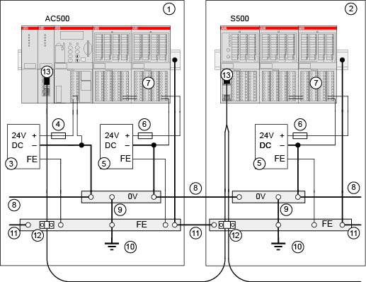
1
Cabinet 1
2
Cabinet 2
3
Power supply for the CPU
4
Fuse for the CPU power
5
Power supply for the I/Os
6
Fuse for the I/O power
7
For fuses for the contacts of the relay outputs
8
0V rail
9
Grounding of the 0V rail
10
Cabinet grounding
11
Equipotential bonding between the cabinets min. 16 mm2
12
Cable shields grounding
13
Fieldbus connection (e.g. Ethernet)