


Automation Builder 2.3 provides an enhanced diagnosis interface for the EtherCAT fieldbus. The user can get EtherCAT diagnosis information from different editor views. All these views are accessible within the EtherCAT master device editor and provide information about the master and all configured or connected slaves. The main diagnosis overview is given in the EtherCAT master view “Diagnostics main”.
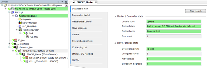
“Diagnostics main” shows EtherCAT state “Operate”.
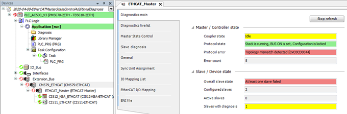
“Diagnostics main” shows EtherCAT state “Topology error’”.
If the EtherCAT bus state shows “Operate”, the user does not need to check for any more information.
If the “Diagnostics main” shows any error, like “Topology mismatch detected”, the user can continue to the next level of information by opening editor view “Master State Control”.
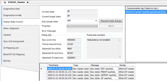
“Master State Control” shows EtherCAT state “Operate”.
“Master State Control” shows EtherCAT state “Toplogy error”.
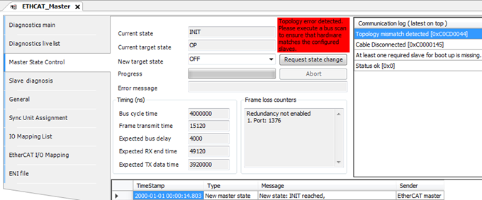
In editor view “Master State Control” the user can request a master state change or get information about configured parameters as well as events and latest communication errors. In case of any topology error (e.g. slaves are configured in a different order than they exist in hardware) the Automation Builder shows a hint to the user that it might be helpful to execute a bus scan in editor view “Diagnostics live list” to compare the scan result of the real hardware with the configures slaves in the Automation Builder project.
Bus scan result in editor view “Diagnostics live list” shows the connected hardware.
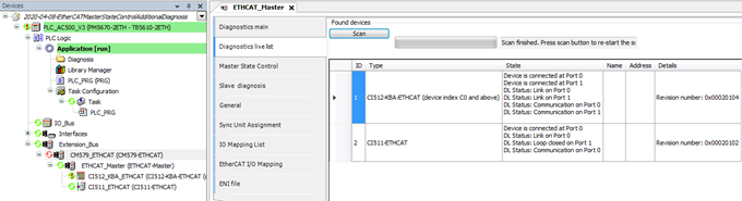
The bus scan result list shows the following information for each connected slave:
|
ID |
Position of the found slave device |
|
|
Type |
Slave identification (name or Vendor/Device ID number) |
|
|
State |
The connection/link state of all ports (0-3) of the given slave |
|
|
Connected |
=> Cable is plugged in |
|
|
+ Link |
=> Physically connected to another slave |
|
|
+ Communication |
=> Communication works fine |
|
|
Name |
Not used for EtherCAT |
|
|
Address |
Not used for EtherCAT |
|
|
Details |
E.g. revision number of the slave device |
|
The bus scan shows information about the real connected hardware.
Note that a bus scan will always restart the EtherCAT bus.
This should not be a problem during commissioning but it might not be applicable in a running system.
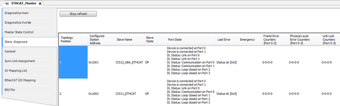
For runtime diagnosis the Automation Builder provides cyclic information of all configured slaves and their states in the editor view “Slave diagnosis”.
Slave diagnosis information shows that configured slaves are ok.
“Slave diagnosis” view shows wrong slave at position 1.
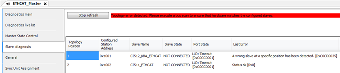
The editor view “Slave diagnosis” shows information about the configured slaves. If these slaves are found in hardware, the states of all slaves are ok. If there is a mismatch between hardware and configuration the view shows at which position that mismatch was detected.
The “Slave diagnosis” shows the following information for each configured slave:
|
Topology Position |
Position of the configured slave device. |
|
|
Configured Station Address |
Address that is defined by configuration. This address is not topology dependent. |
|
|
Slave Name |
Configured name of the slave device. |
|
|
Slave State |
The state of the slave. Possible slave states are: |
|
|
|
||
|
|
||
|
|
||
|
|
||
|
|
||
|
|
||
|
|
||
|
|
||
|
Port State 2) |
The state of all ports (0-3) of the given slave. |
|
|
Shows how many connections this slave has to other slaves and if the connections are working fine: |
||
|
Connected |
=> Cable is plugged in |
|
|
+ Link |
=> Physically connected to another slave |
|
|
+ Communication |
=> Communication works fine |
|
|
Last Error |
The last error that occurred in this slave. As text, if available, and error number. If this is any topology error, the editor view will show a hint to perform a bus scan. |
|
|
Emergency [CAN application protocol over EtherCAT (CoE)] |
This column contains up to 5 CoE emergency entries. Each entry has |
|
|
Error code |
||
|
Address of the error register |
||
|
Error data (1 byte) |
||
|
If there are more than five emergencies reported by the slave, the columns show a hint that some emergency entries have been lost. The column is empty, if no CoE emergencies exist. |
||
|
Frame Error Counters 2) |
Counts transmission errors on frame layer, detected by CRC check of frames. Fast growing values show a serious problem. Possible root causes include damaged cables, high electromagnetic noise or misbehavior of EtherCAT slave devices. Four counter values are shown, one for each port 0-3. Column has red background in case of any value other than 0. |
|
|
Physical Layer Error Counters 2) |
Counts transmission errors on physical layer. Possible root causes include electromagnetic disturbance or faulty devices. Four counter values are shown, one for each port 0-3. Column has red background in case of any value other than 0. |
|
|
Link Lost Counters 2) |
Optional feature of EtherCAT slave devices, not supported by every device. |
|
|
Counts loss of physical connection (no link, LED off). Even short interruptions can be detected. Possible root causes include power dips, device reset, poor cables or connectors, loose contact. Four counter values are shown, one for each port 0-3. Column has red background in case of any value other than 0. |
||
1) Note that columns “Port State”, “Frame Error Counters”, “Physical Layer Error Counters” and “Link Lost Counters” show “LLD: Timeout”, if this state is NOT CONNECTED, because this information is not accessible.
2) Note that this column contains “LLD: Timeout”, if slave state is NOT CONNECTED.
General note on the counters
General note on the counters
Please note that this kind of errors will be detected by devices when power state changes, e.g. when the device itself or a neighboring device is powered on, caused by switching artifacts on the cable. This does not signal an issue, only counters increasing during normal operation should trigger deeper analysis. Counters can be reset by the PLC program using corresponding function blocks.