


The EtherCAT state is shown by the EtherCAT communication module's LEDs. Some LEDs are two-colored.
|
LED |
Color |
State |
Description |
|
|---|---|---|---|---|
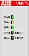 |
PWR |
Green |
On |
Power supply available |
|
Blinking |
--- |
|||
|
Off |
Power supply not available or defective hardware |
|||
|
RDY |
Yellow |
On |
Boot procedure |
|
|
Blinking |
Boot failure |
|||
|
Off |
--- |
|||
|
RUN |
Green |
On |
Communication module is operational |
|
|
Blinking |
--- |
|||
|
Off |
Communication module is not operational |
|||
|
STA1 |
Green |
On |
No bus error, communication running |
|
|
Blinking |
Establishing communication |
|||
|
Off |
System error |
|||
|
STA2 |
Red |
On |
Configuration error |
|
|
Blinking |
--- |
|||
|
Off |
No error |
|||
|
STA1 |
Yellow |
Blinking (synchronously) |
No production data available, no bus communication possible. |
|
|
STA2 |
Yellow |
|||
|
LED state during firmware update |
STA1 |
Green |
Blinking (synchronously) |
Firmware file transfers during communication module firmware update. |
|
STA2 |
Red |
|||
|
STA1 |
Green |
Blinking (alternately) |
Communication module writes the firmware file to the internal flash. Do not power off the PLC! |
|
|
STA2 |
Red |
|||
The RJ45 Ethernet connector contains two LEDs showing the current Ethernet port connection state.
|
LED |
Color |
State |
Description |
|
|---|---|---|---|---|
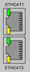 |
ETHCAT1 LED "Link" |
Green |
On |
Ethernet connection established |
|
Off |
No Ethernet connection |
|||
|
ETHCAT1 LED "RX/TX" |
Yellow |
On |
Device sends/receives frames |
|
|
Off |
No Ethernet connection |
|||
|
ETHCAT2 LED "Link" |
Green |
Connector ETHCAT2 is not used |
||
|
ETHCAT2 LED "RX/TX" |
Yellow |
|||