


Requirement: A device that supports an I/O mapping configuration in CODESYS is inserted in the device tree of your project. On the “I/O Mapping” tab in the device editor you thus get a tabular display of the input and output channels of the device with specification of the addresses and data types.

NOTICE
Mapping data types which are "too large"
If a variable of a data type that is larger than a byte is mapped to a byte address, the value of the variable will be truncated to byte size there. For monitoring the variable value in the “I/O Mapping” dialog, this means that, in the "root" element of the address, the value is displayed which the variable currently has in the project. The current individual bit values of the byte are displayed in succession in the bit elements below that, but this may not be sufficient for the entire variable value.
If a UNION is represented by I/O channels in the mapping dialog, it depends on the device whether mapping to the "root" element is also possible.
-
In a POU, declare, for example, a variable
xBool4of the typeBOOLwith which you want to access an input of the target device from the application. -
To open the device editor, double-click the device object in the device tree, and then the “<device name> I/O Mapping” tab.
-
Observe the “Variable” column with the display of the device input
 channels and device output
  channels , which can still be sorted by organizational
  nodes, depending on the device. We assume that there is a device input of the type
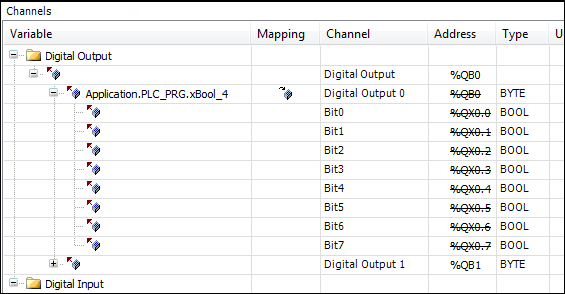
BYTE. It is displayed with its individual bit addresses (bit channels) below theBYTEnode. -
Note: When mapping structured variables, the editor prevents you from entering both the structure variable (example:
%QB0) and individual structure elements (example:%QB0.1andQB0.2). Therefore, if there is a main entry with a subtree of bit channel entries in the mapping table, then the following applies: Then you can specify a variable either into the line of the main entry, or into the lines of the subelements (bit channels), but not into both.You can now occupy either the entire channel with a variable of a suitable type OR its individual bit-channel addresses with suitable variables of the type
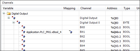
BOOLorBIT. First of all, double-click a bit input channel in the “Variables” column.An input field opens.
-
In order to place an existing variable on the channel, you have to enter the desired project variable with the complete path. Press
 to open the Input Assistant. Select, for example, the variable
 Application.PLC_PRG.xBool4declared inPLC_PRG.The variable is inserted. The
 symbol is displayed in the “ Mapping” column. The address is now struck through. That does not mean that the address is
no longer available, because values of existing variables are managed at another memory
space. But: in order to avoid ambiguities when writing the values, you should nevertheless
not occupy the address with a further variable, especially in the case of outputs.
symbol is displayed in the “ Mapping” column. The address is now struck through. That does not mean that the address is
no longer available, because values of existing variables are managed at another memory
space. But: in order to avoid ambiguities when writing the values, you should nevertheless
not occupy the address with a further variable, especially in the case of outputs.
Note: For compiler version V3.5 SP11 and higher, the initialization value of the variables is used automatically as the default value when mapping to an existing variable. You can edit the “Default value” field only if you map to a new created variable or if no mapping is specified. In older versions, users had to specify explicitly that the default value and initialization value were identical.
-
Delete the variable assignment again. Click the root of the channel, the
BYTEnode. Use the Input Assistant again to select the variableApplication.PLC_PRG.byte_gotodevice.The variable is inserted, all bit addresses of the main channel are struck through and you should not additionally occupy them.
-
See also: ⮫ I/O Mapping