


The onboard I/Os support the following channel functions according to the processor module type.
|
Onboard I/O type |
Channel function |
PM5012-T-ETH |
PM5012-R-ETH |
Channel name when available |
|---|---|---|---|---|
|
Digital input channel total thereof as |
Digital input |
6 |
6 |
DI0 … DI5 |
|
Fast input x, max. 5 kHz |
Digital input |
6 |
6 |
DI0 … DI5 |
|
Interrupt input |
4 |
4 |
DI0 … DI3 |
|
|
Fast counter |
2 |
2 |
DI4 … DI5 |
|
|
Digital output channel total thereof as |
Digital output |
4 |
4 |
DO0 … DO3 |
|
Fast output x, max. 5 kHz |
Digital output |
4 |
4 |
DO0 … DO3 |
|
Limit switch |
4 |
- |
DO0 … DO3 |
|
|
PWM output |
4 |
- |
DO0 … DO3 |
|
Onboard I/O type |
Channel function |
PM5032-T-ETH PM5052-T-ETH PM5072-T-2ETH(W) PM5082-T-2ETH |
PM5032-R-ETH PM5052-R-ETH |
Channel name when available |
|---|---|---|---|---|
|
Digital input channel total |
Digital input |
12 |
12 |
DI0 … DI11 |
|
Fast input x, max. 5 kHz |
Digital input |
4 |
4 |
DI0 … DI3 |
|
Interrupt input |
4 |
4 |
DI0 … DI3 |
|
|
Touch/Reset |
4, together with dedicated encoder |
4, together with dedicated encoder |
DI0 … DI3 |
|
|
Fast input x, max. 100 kHz |
Digital input |
4 |
4 |
DI4 … DI7 |
|
Encoder input |
2, with A/B tracks |
2, with A/B tracks |
DI4 … DI7 |
|
|
Fast counter |
4 |
4 |
DI4 … DI7 |
|
|
Standard input |
Digital input |
4 |
4 |
DI8 … DI11 |
|
Digital output channel total |
Digital output |
8 |
6 |
DO0 … DO7 DO0 … DO5 |
|
Fast output x, max. 5 kHz |
Digital output |
4 |
- |
DO0 … DO3 |
|
Limit switch |
4 |
- |
DO0 … DO3 |
|
|
PWM output |
4 |
- |
DO0 … DO3 |
|
|
Fast output x, max. 100 ... 200 kHz |
Digital output |
4 |
- |
DO4 … DO7 |
|
Limit switch |
4 |
- |
DO4 … DO7 |
|
|
PWM output |
4 |
- |
DO4 … DO7 |
|
|
PTO output |
2, pair of output, in CW/CCW or Pulse/Direction mode or 4 as Pulse with standard outputs as Direction |
- |
DO4 … DO7 |
|
|
Digital in/output configurable channel total |
Digital in/output |
2 |
2 |
DC12 … DC13 |
|
Standard dig. channel |
Digital In/output |
2 |
2 |
DC12 … DC13 |
|
Fast output, max. 100 ... 200 kHz |
Limit switch |
- |
2 |
DC12 … DC13 |
|
PWM output |
- |
2 |
DC12 … DC13 |
|
|
PTO output |
- |
1, pair of output, in CW/CCW or Pulse/Direction mode |
DC12 … DC13 |
When debugging AC500-eCo applications and reaching a breakpoint, the onboard outputs are set to zero.
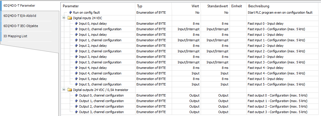
Basic CPU: PM5012-x-ETH
For all CPU versions, the configuration of the input channels is identical. The configuration of the output channels is available only for CPU version with transistor output channels.
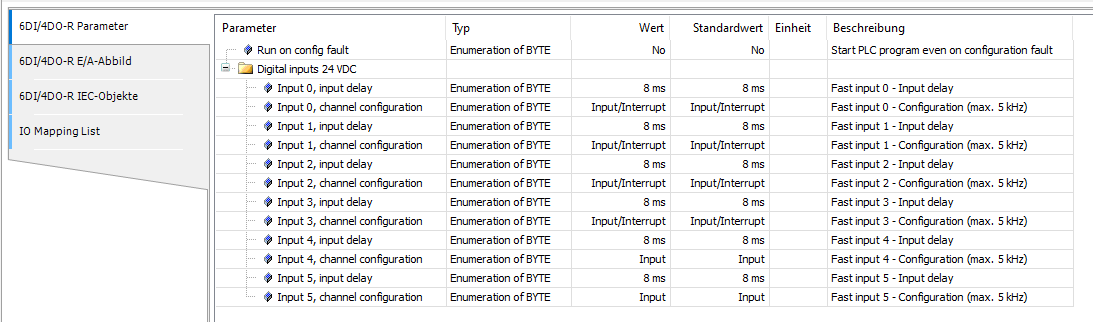
Version with relay outputs
For CPU versions with relay outputs, the configuration of the input channels is identical. No configuration is available for relay output channels.
Configurable parameters
The following parameter can be configured.
|
Onboard I/O type |
Parameter |
Channel name |
Default value |
Value |
Description |
|---|---|---|---|---|---|
|
Digital inputs |
Input X, input delay |
Channel 0..5 |
8 ms |
No delay |
Configures input with no delay. |
|
1 ms |
Configures 1 ms input delay. |
||||
|
8 ms |
Configures 8 ms input delay. |
||||
|
32 ms |
Configures 32 ms input delay. |
||||
|
Input X, channel configuration |
Channel 0..3 |
Input/Interrupt |
Input/Interrupt |
Configures the channel as normal digital or interrupt input. |
|
|
The configuration /function of the following channels is realized using function blocks in the program |
Channel 4..5 |
Input |
Input |
Configures the channel as normal digital input. |
|
|
Encoder 0 track-A or B |
Configures the pair of channels as encoder input track A or B. When that value is configured then both channels are reserved for that functionality. |
||||
|
Forward counter |
Configures the channel as forward counter. |
||||
|
The configuration of output channel is only available on the CPU with transistor outputs |
|||||
|
Digital outputs |
Output X, channel configuration |
Channel 0..3 |
Output |
Output |
Configures the channel as digital output. |
|
Limit switch |
Configures the channel as limit switch output. |
||||
|
PWM |
Configures the channel as PWM output. |
||||
Standard CPU: PM5032-x-ETH, PM5052-x-ETH Pro CPU: PM5072-T-2ETH, PM5082-T-2ETH
For all CPU versions the configuration of the input channels is the same. The configuration of the output channels is only available on CPU version with transistor output channels, the digital configurable In/Output channels are present on both version (transistor or relay output) but with different features configurable:
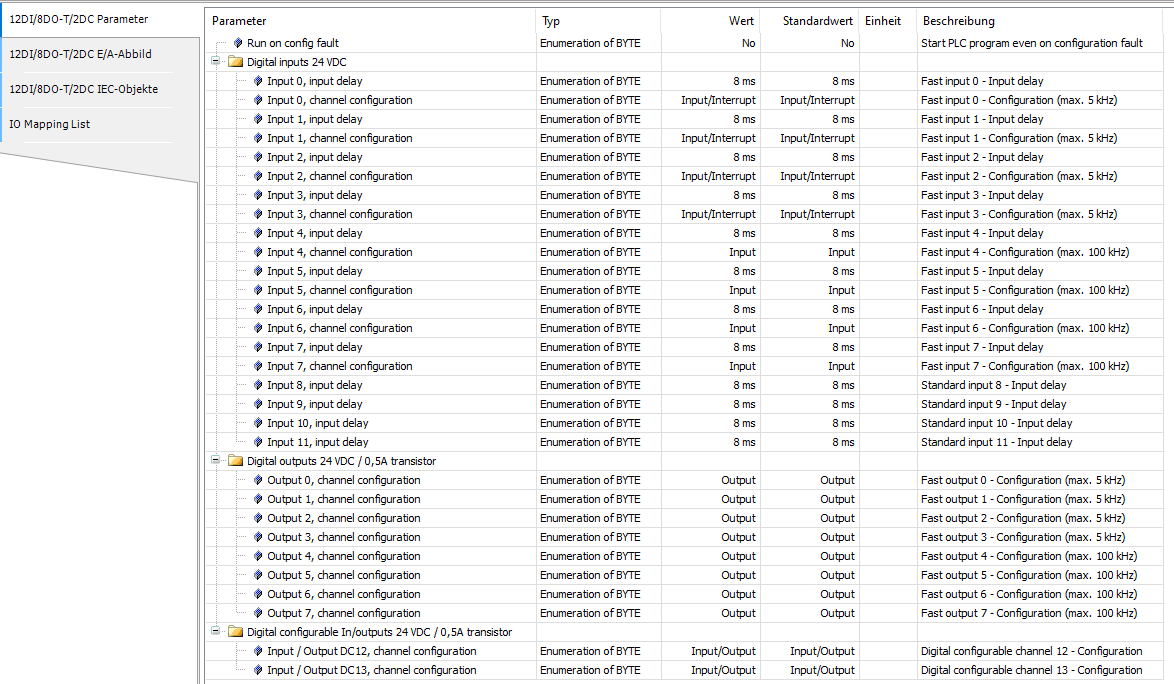
For the CPU with relay outputs, the digital configurable Input/Output channels have specific functionalities:
|
Onboard I/O type |
Parameter |
Channel name |
Default value |
Value |
Description |
|---|---|---|---|---|---|
|
Digital inputs |
Input X, input delay |
Channel 0..11 |
8 ms |
No delay |
Configures input with no delay. |
|
1 ms |
Configures 1 ms input delay. |
||||
|
8 ms |
Configures 8 ms input delay. |
||||
|
32 ms |
Configures 32 ms input delay. |
||||
|
Fast inputs max. 5 kHz |
Input X, channel configuration |
Channel 0..1 |
Input/Interrupt |
Input/Interrupt |
Configures the channel as normal digital or interrupt input. |
|
Touch/Reset 0 |
Configures the pair of adjacent channels as Touch/Reset inputs together with encoder 0. |
||||
|
Channel 2..3 |
Input/Interrupt |
Input/Interrupt |
Configures the channel as normal digital or interrupt input. |
||
|
Touch/Reset 1 |
Configures the pair of adjacent channels as Touch/Reset inputs together with encoder 1. |
||||
|
Fast inputs max. 100/200 kHz |
The function of the following channels is realized using function blocks in the program |
Channel 4..5 |
Input |
Input |
Configures the channel as normal digital input. |
|
Max. frequency 200 kHz |
When that value is configured then both channels are reserved for that functionality |
Encoder 0 track-A or B |
Configures the pair of adjacent channels as encoder 0 input track A or B. |
||
|
Max. frequency 100 kHz |
Forward counter |
Configures the channel as forward counter. |
|||
|
Fast inputs max. 100/200 kHz |
Channel 6..7 |
Input |
Input |
Configures the channel as normal digital input. |
|
|
Max. frequency 200 kHz |
When that value is configured then both channels are reserved for that functionality |
Encoder 1 track-A or B |
Configures the pair of adjacent channels as encoder 1 input track A or B. |
||
|
Touch/Reset |
Configures the pair of adjacent channels as Touch/Reset inputs together with encoder 0. |
||||
|
Max. frequency 100 kHz |
Forward counter |
Configures the channel as forward counter. |
|||
|
The following configuration of output channel is only available on the CPU with transistor. |
|||||
|
Fast outputs, max. 5 kHz |
Output X, channel configuration |
Channel 0..3 |
Output |
Output |
Configures the channel as digital output. |
|
The configuration / function of the following channels is realized using function blocks in the program |
Limit switch |
Configures the channel as limit switch output. |
|||
|
PWM |
Configures the channel as PWM output. |
||||
|
Fast outputs max. 100/200 kHz |
Output X, channel configuration |
Channel 4..7 |
Output |
Output |
Configures the channel as digital output. |
|
The function of the following channels is realized using function blocks in the program |
Limit switch |
Configures the channel as limit switch output. |
|||
|
Max. frequency 100 kHz |
PWM |
Configures the channel as PWM output. |
|||
|
Max. frequency 100/200 kHz |
Depending on the OBIOMotionPTO or OBIOMotionPWM function block used |
PTO |
Configures the pair of adjacent channels as PTO output or one as pulse and a standard output as direction. |
||
|
Digital configurable input/outputs |
Output X, channel configuration |
Channel DC12..DC13 |
Input/Output |
Input/Output |
Configures the channel as digital input/output. |
|
The following configuration of output channel is only available on the CPU with relay outputs |
|||||
|
Digital configurable input/outputs |
Output X, channel configuration |
Channel DC12..DC13 |
Input/Output |
Input/Output |
Configures the channel as digital input/output. |
|
The function of the following channels is realized using function blocks in the program |
Limit switch |
Configures the channel as limit switch output. |
|||
|
Max. frequency 100 kHz |
PWM |
Configures the channel as PWM output. |
|||
|
Max. frequency 100/200 kHz |
Depending on the OBIOMotionPTO or OBIOMotionPWM function block used |
PTO |
Configures the pair of channels as PTO output. |
||