

DNP3 Outstation devices are often required to time tag the datapoint events to the nearest milliseconds. To support these time-related activities, an outstation shall have a dependable time source. It may use a local source, such as GPS receiver, or it can request time synchronization from the master using DNP3 messages or polling.
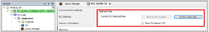
By default, in a controller always has time set internally to “1970-01-01 01:00:00. In the AC500 PLCs, user can set the PLC time using several ways.
-
Login to the PLC and use the Statistics tab to set the PLC time to PC time.
-
If a (S)NTP server (e. g. Meinberg clock) is available in the network, the AC500 should be configured as (S)NTP client in order to receive the correct time information from the server connected.
In specific to the DNP3 Protocol time synchronization (Object group 50, 51 and 52) is also supported as per the DNP3 standards. In this case, master can send Time sync to the outstations periodically.
LAN based time synchronization
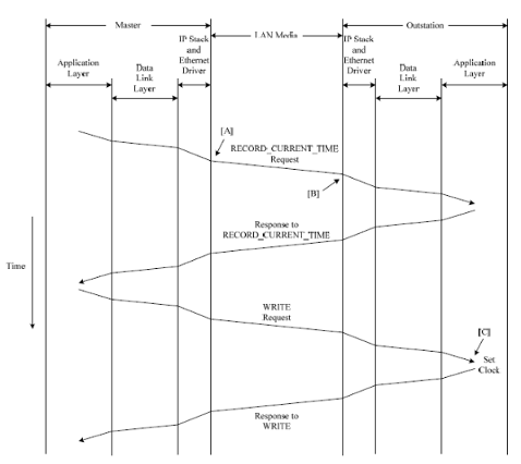
The above figure the sequence and relative timing of messages used to time synchronize an outstation from the master. Two separate request messages are transmitted from the master, record current time and write. The first requests the outstation to record the time of receipt of the last octet in the message, and the second sends the time that the message should have arrived at the outstation.
A different method is used for time synchronization over a LAN than is used in non-LAN applications. The reasons are that the propagation delay measurement is negligible and that recording the time at the first bit of the first octet does not account for network collisions.
There are three critical time points in the sequence. Letters inside square brackets [A] through [C] show these. [A] represents the instant when the last message octet has left the Ethernet hardware, and [B] represents the instant when the last octet of the message is received in the Ethernet hardware. The last octet is the second octet of the last CRC value in a Data Link Layer frame. [C] represents the instant when the clock is set.
The steps for time synchronization are as follows:
-
The master sends a message having function code RECORD_CURRENT_TIME. The master records the time when the last octet leaves the Ethernet hardware. This is critical time point [A] in the diagram.
-
The outstation records the time (or starts a timer) when the last octet of the request arrives in its Ethernet hardware. This is critical time point [B] in the diagram.
-
The outstation sends a null response.
-
The master sends a message having function code write with a last recorded time and date object, group 50, variation 3. The value in this object contains the time that master recorded in step 1.
-
The outstation sets its internal clock using the time in write request and knowing the difference in time between critical time points [B] and [C]. Critical time point [C] is the instant when the clock is set, the outstation’s time is calculated as:
Time in request + (Number of milliseconds from [B] to [C])
-
The outstation sends a null response. IIN1.4 [NEED_TIME] should be cleared in this response.
-
When multiple master sessions are connected to the same outstation, user can select the master which is allowed to the time synchronization. User can enable this at the master session configuration.
-
Clock valid period input can be used to define the validity period of the last time synchronization received by an Outstation from the master.