


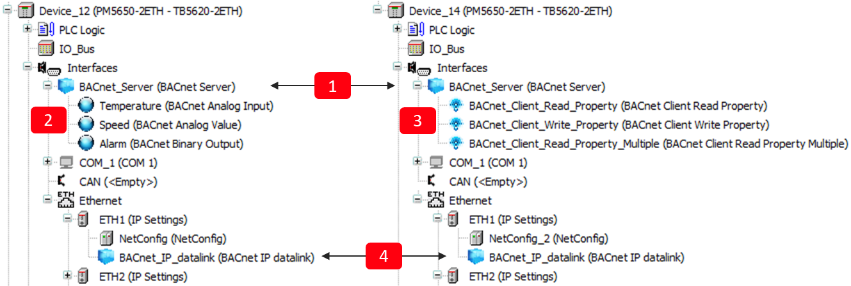
To act as a BACnet server or client, the AC500 must be configured accordingly. The figure below shows the basic configuration of a BACnet server (left) and a BACnet server with client functionality (right). It is also possible to have server and client functionality in parallel.
Following objects need to be created:
1
“BACnet Server” root object. This is the root object for the server functionality, as well as for the client functionality. It is mandatory, even if only client functionality is required. ⮫ “Configuration of BACnet server root object ”
2
BACnet server objects, for example “BACnet Analog Input” Temperature. The properties of the objects must be controlled (written or read) by the PLC logic.
⮫ “Adding BACnet server objects”
3
BACnet client objects, represented by a different symbol. For example, “BACnet Client Read Property”. The functionality of the client objects must be programmed in the PLC logic. Inserting the client objects below the server is optional. It is also possible to instantiate the objects only in a PLC logic. ⮫ “Adding BACnet client functionality”
4
Datalink for the physical layer. This object links the physical interface (Ethernet IP or serial MS/TP) to the “BACnet Server” object. In the example above the IP address of ETH1 is automatically retrieved by inserting the “BACnet IP datalink” below the ETH1 port. ⮫ “Configuration of an IP datalink”. For MS/TP refer to ⮫ “Configuration of an MS/TP datalink”.