You can animate a visualization element and have it shifted or rotated at runtime. To do this you assign variables in its property “Absolute movement” and then program the animation in the application code.
Configuring an offset
You can configure an offset of the element by programming the variables in “Absolute movement Movement”.
Requirement: A project with a visualization is open.
-
Open the visualization and add an element “Rectangle”.
The view “Properties” displays the configuration of the element.
-
In the application in the POU
PLC_PRG, declare type-compliant variables: diOffsetX : DINT;anddiOffsetY : DINT; -
Configure the property “Absolute movement Movement X” with
PLC_PRG.diOffsetXand “Y” withPLC_PRG.diOffsetY. -
Implement a shift of the element, for example by means of a modulo division of the value:
diOffsetX := diOffsetX MOD 100;
diOffsetY := diOffsetY MOD 100;
-
Compile, load and start the application.
The application runs. The visualization opens. The rectangle moves.
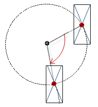
Configuring a rotating element
When an element rotates, then the center point of the element rotates precisely around its center. The center is defined in the property “Center”. The center point of an element is calculated internally. If the center point and center coincide, then there is no rotation.
You can configure a clockwise rotation of the element by increasing the value of the variable “Absolute movement Rotation”.
Requirement: A project with a visualization is open.
-
Open the visualization and add an element “Rectangle”.
The view “Properties” displays the configuration of the element.
-
In the application in the POU
PLC_PRG, declare a type-compliant variable:rValue : REAL; -
Configure the property “Absolute movement Rotation” with
PLC_PRG.rValue. -
Implement the clockwise rotation of the element by increasing the value of the variable:
rValue := rValue + 0.1; -
Compile, load and start the application.
The application runs. The visualization opens. The rectangle rotates about the center. The alignment of the element with respect to the coordinate system is fixed.
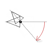
Configuring a rotating element
When an element performs an inner rotation and rotates, then the center point of the element rotates precisely around its center. This is the point defined in the property “Center”. The alignment of the element also rotates relative to the coordinate system. If the center point of the element and the center coincide, this produces a rotation on the spot.
You can configure a clockwise rotation of the element by increasing the value of the variable “Absolute movement Inner rotation”.
If the visualization is In runtime, you can see that the element rotates (also relative to the coordinate system of the visualization).
Requirement: A project with a visualization is open.
-
Open the visualization and add an element “Polygon”, which you form into a pointer.
The view “Properties” displays the configuration of the element.
-
Drag the center point of the element to the base of the pointer.
-
In the application in the POU
PLC_PRG, declare a type-compliant variable:rValue : REAL; -
Configure the property “Absolute movement Inner rotation” with
PLC_PRG.rValue. -
Implement the clockwise rotation of the element by increasing the value of the variable:
rValue := rValue + 0.1;
-
Compile, load and start the application.
The application runs. The visualization opens. The pointer rotates about its base.