


Make sure that the address is valid as follows:
To map a valid address in an application, you first need to know the required position in the process image. This means the applicable memory area: input memory area (I), output memory area (Q), or flag memory area (M) (see above). Furthermore, you need to specify the required size prefix: bit, BYTE, WORD, DWORD (see above: X, B, W, D)
The currently used device configuration and device settings (hardware structure, device description, I/O settings) play a decisive part.
Pay special attention to the differences in the interpretation of bit addresses between devices with byte addressing and devices with word-oriented IEC addressing.
In the case of the bit address %IX5.5, the number before the dot addresses byte 5 in a byte-addressed device and word 5 in a word-addressed device.
In contrast, addressing with a word or byte address is independent of the device type: with %IW5, word 5 is always addressed, and with byte address %IB5 always byte 5. Depending on the size and addressing mode, you can therefore address different memory cells with the same address information.
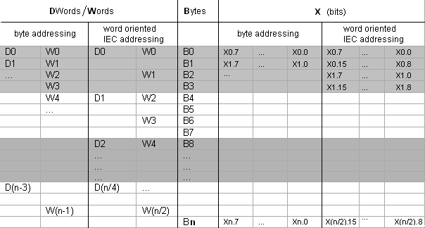
The following table shows the comparison of byte addressing and word-oriented IEC addressing for bits, bytes, words, and double words. It also shows the overlapping memory areas for byte addressing. See the example at the end of the table.
Concerning syntax, note that the IEC addressing is always word-oriented. The word number is located before the dot, and the bit number after the dot.
n = byte number
Example of overlapping memory areas for byte addressing
D0 contains B0 - B3. W0 contains B0 and B1. W1 contains B2 and B3. W2 contains B4 and B5.
W1, but also D1, D2, and D3 must not be used for addressing. This avoids overlapping.